
Page 1075 - Softbound_Edition_19_en
P. 1075
Proportional
pressure reducing valves
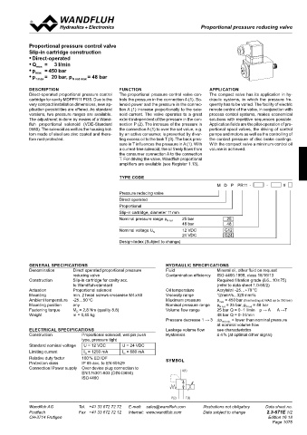
Proportional pressure reducing valve
Proportional pressure control valve
Slip-in cartridge construction
• Direct-operated
• Q max = 3 l/min
• p max = 450 bar
• p T max = 20 bar, p N red max = 48 bar
DESCRIPTION FUNCTION APPLICATION
Direct-operated proportional pressure control The proportional pressure control valve con- The compact valve has its application in hy-
cartridge for cavity MDPPR11 PI35. Due to the trols the pressure in the connection A (1). So- draulic systems, in which the pressure fre-
very compact installation dimensions, new ap- lenoid power and the pressure in the connec- quently has to be varied. The facility of electric
plication possibilities are offered. As standard tion A (1) increase proportionally to the sole- remote control of the valve, in conjunction with
versions, two pressure ranges are available. noid current. The valve operates to a great process control systems, makes economical
The adjustment is done by means of a Wand- extent independent of the pressure in the con- solutions with repetitive sequences possible.
fluh proportional solenoid (VDE-Standard nection P (2). The increase of the pressure in Application fields are the pilot-operation of pro-
0580). The solenoid as well as the housing bot- the connection A (1) to over the set value, e.g. portional spool valves, the driving of control
tom made of steel are zinc coated and there- by an active consumer, is prevented by diver- pumps and motors as well as the controlling of
fore rust-protected. ting excess oil to the tank T (3). The back pres- the contact pressure of disc brake coatings.
sure in T influences the pressure in A (1). With With the compact valve a minimum control oil
a current-free solenoid, the oil freely flows from volume is achieved.
the consumer connection A to the connection
T. For driving the valve, Wandfluh proportional
amplifiers are available (see Register 1.13).
TYPE CODE
M D P PR11 - - #
Pressure reducing valve
Direct operated
Proportional
Slip-in cartridge, diameter 11 mm
Nominal pressure range p N red 25 bar 25
48 bar 48
Nominal voltage U N 12 VDC G12
24 VDC 20 G24
Design-Index (Subject to change)
GENERAL SPECIFICATIONS HYDRAULIC SPECIFICATIONS
Denomination Direct operated proportional pressure Fluid Mineral oil, other fluid on request
reducing valve 15 Contamination efficiency ISO 4406:1999, class 18/16/13
50
Construction Slip-in cartridge for cavity acc. Required filtration grade (ß 6...10 ≥ 75)
to Wandfluh-standard 74 (refer to data sheet 1.0-50/2)
Actuation Proportional solenoid Oil temperature Acrylnitril -25…+70 °C
40
Mounting min. 2 head screws crosswise M4 x 60 Viscosity range 12 mm /s...320 mm /s 30
2
2
Ambient temperature -25…50 °C Maximum pressure p max = 450 bar (final testing at WAG up to 350 bar)
T(3)
Mounting position any Nominal pressure range p N red = 25 bar, p N red = 48 bar
A(1)
Fastening torque M D = 2,8 Nm (quality 8.8) Volume flow range 25 bar Q = 0 - 1 l/min p → A A →T
Weight m = 0,45 kg 48 bar Q = 0 -3 l/min
Pressure decrease 1 → 3 ∆p red min. < lower than nominal pressure
P(2)
at nominal volume flow
ELECTRICAL SPECIFICATIONS Leakage volume flow see characteristics
Construction Proportional solenoid, wet pin push Hysteresis 70,3 ≤ 4 % (at optimal dither signal)
14
type, pressure tight
Standard nominal voltage U = 12 VDC U = 24 VDC
Limiting current I G = 1250 mA I = 680 mA
G
Relative duty factor 100 % ED / DF SYMBOL
Protection class IP 65 acc. to EN 60 529
Connection / Power supply Over device plug connection to
EN 175301-803 (DIN 43650) A(1)
ISO 4400
P(2) T(3)
Wandfluh AG Tel. +41 33 672 72 72 E-mail: sales@wandfluh.com Illustrations not obligatory Data sheet no.
Postfach Fax +41 33 672 72 12 Internet: www.wandfluh.com Data subject to change 2.3-671E 1/2
CH-3714 Frutigen Edition 16 18
Page 1075