Page 1074 - Softbound_Edition_19_en
P. 1074

Proportional
                                                                          Proportional pressure reducing valve
                                                                         Proportional pressure reducing valve                                                                                                     pressure reducing valves


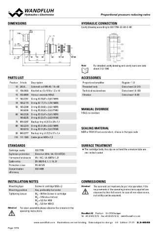
       DIMENSIONS                                          HYDRAULIC CONNECTION                                                    Proportional pressure control valve
                                                           Cavity drawing according to ISO 7789–33–04–0–98                         Slip-in cartridge construction
                                                                                                                                   • Direct-operated
             110                                                                  M33x2                                            • Q    =   3 l/min
                                       s32                                                                                            max
           70.8                        M33x2                                                                                       • p max   = 450 bar
         93.3   15                         (3)  (2)                                                                                • p T max  =  20 bar, p N red max  = 48 bar
           MD=5.5Nm                                                                     (3)
                                                    (1)                                                                            DESCRIPTION                        FUNCTION                           APPLICATION
           22.5                                                                         (2)                                        Direct-operated proportional pressure control   The proportional pressure control valve con-  The compact valve has its application in hy-
                                                                                                                                   cartridge for cavity MDPPR11 PI35. Due to the   trols the pressure in the connection A (1). So-  draulic  systems,  in  which  the  pressure  fre-
             12    17  18  10  18     50   70  60   90  80                                                                         very compact installation dimensions, new ap-  lenoid power and the pressure in the connec-  quently has to be varied. The facility of electric
           MD=9Nm                                                                       (1)                                        plication possibilities are offered. As standard   tion A (1) increase proportionally to the sole-  remote control of the valve, in conjunction with
                            60
                            96.4            77.9                                   (1)                                             versions, two pressure ranges are available.   noid current. The valve operates to a great   process control systems, makes economical
                                  181.2                    Note!         For detailed cavity drawing and cavity tools see data     The adjustment is done by means of a Wand-  extent independent of the pressure in the con-  solutions with repetitive sequences possible.
                                                                    sheet 2.13-1040                                                fluh proportional solenoid (VDE-Standard   nection P (2). The increase of the pressure in   Application fields are the pilot-operation of pro-
                                                                                                                                   0580). The solenoid as well as the housing bot-
                                                                                                                                                                      the connection A (1) to over the set value, e.g.
                                                                                                                                                                                                         portional spool valves, the driving of control
                                                                                                                                   tom made of steel are zinc coated and there-  by an active consumer, is prevented by diver-  pumps and motors as well as the controlling of
                                                                                                                                   fore rust-protected.               ting excess oil to the tank T (3). The back pres-  the contact pressure of disc brake coatings.
       PARTS LIST                                          ACCESSORIES                                                                                                sure in T influences the pressure in A (1). With   With the compact valve a minimum control oil
                                                                                                                                                                      a current-free solenoid, the oil freely flows from   volume is achieved.
        Position Article  Description                       Proportional amplifier       Register 1.13                                                                the consumer connection A to the connection
            10 263.6...  Solenoid coil MK.45 / 18 x 60      Threaded body                Data sheet 2.9-210                                                           T. For driving the valve, Wandfluh proportional
                                                                                                                                                                      amplifiers are available (see Register 1.13).
            12 154.2603  Knurled nut Ex M18 x 1,5 x 18      Technical explanations       Data sheet 1.0-100
            15 253.8000  Manual override HB4,5              Filtration                   Data sheet 1.0-50                                                            TYPE CODE
            17 160.2251  O-ring ID 25,07 x 2,62 (NBR)                                                                                                                                                       M  D  P  PR11  -       -     #
            18 160.2170  O-ring ID 17,17 x 1,78 (NBR)                                                                                                                 Pressure reducing valve
            50 160.2298  O-ring ID 29,82 x 2,62 (NBR)                                                                                                                 Direct operated
               160.6296  O-ring ID 29,82 x 2,62 (FMK)      MANUAL OVERRIDE                                                                                            Proportional
                                                           HB4,5 as standard
            60 160.2235  O-ring ID 23,47 x 2,62 (NBR)                                                                                                                 Slip-in cartridge, diameter 11 mm
               160.6235  O-ring ID 23,47 x 2,62 (FKM)                                                                                                                 Nominal pressure range p N red    25 bar       25
            70 049.3297  Backup ring rd 24,5 x 29 x 1,4                                                                                                                                        48 bar               48
                                                                                                                                                                      Nominal voltage U        12 VDC             G12
            80 160.2219  O-ring ID 21,89 x 2,62 (NBR)                                                                                                                              N           24 VDC             G24
               160.6216  O-ring ID 21,89 x 2,62 (FKM)      SEALING MATERIAL                                                                                           Design-Index (Subject to change)      20
            90 049.3277  Backup ring rd 22,5 x 27 x 1,4    NBR or FKM (Viton) as standard, choice in the type code
           110 111.1080  Cable gland M20 x 1,5

                                                                                                                                   GENERAL SPECIFICATIONS                               HYDRAULIC SPECIFICATIONS
       STANDARDS                                           SURFACE TREATMENT                                                       Denomination     Direct operated proportional pressure   15  Fluid       Mineral oil, other fluid on request
       Cartridge cavity   ISO 7789                          ◆  The cartridge body, the slip-on coil and the armature tube are        Construction   reducing valve                      Contamination efficiency   ISO 4406:1999, class 18/16/13
                                                                                                                                                                                                                     50
                                                                                                                                                                                                            Required filtration grade (ß 6...10 ≥ 75)
                                                                                                                                                    Slip-in cartridge for cavity acc.

       Explosion protection  Directive 2014 / 34 / EU (ATEX)  zinc-nickel coated                                                                    to Wandfluh-standard    74                              (refer to data sheet 1.0-50/2)
                                                                                                                                                                                                                       40
       Flameproof enclosure  EN / IEC / UL 60079-1, 31                                                                             Actuation        Proportional solenoid               Oil temperature     Acrylnitril -25…+70 °C
                                                                                                                                                                                                                 /s...320 mm /s 30
                                                                                                                                                                                        Viscosity range
                                                                                                                                   Mounting
                                                                                                                                                    min. 2 head screws crosswise M4 x 60
                                                                                                                                                                                                                          2
       Cable entry        EN 60079-0, 1, 7, 15, 31                                                                                 Ambient temperature   -25…50 °C                      Maximum pressure    12 mm 2  T(3)
                                                                                                                                                                                                                = 450 bar (final testing at WAG up to 350 bar)
                                                                                                                                                                                                            p max
       Protection class   EN 60 529                                                                                                Mounting position   any                              Nominal pressure range   p N red  = 25 bar, p N red  = 48 bar
                                                                                                                                                                                                                            A(1)
       Contamination      ISO 4406                                                                                                 Fastening torque   M D  = 2,8 Nm (quality 8.8)       Volume flow range   25 bar Q = 0 - 1 l/min  p → A   A →T
                                                                                                                                                                                                            48 bar Q = 0 -3 l/min
                                                                                                                                   Weight
                                                                                                                                                    m = 0,45 kg

       efficiency                                                                                                                                                                       Pressure decrease 1 → 3  ∆p red min.  < lower than nominal pressure
                                                                                                                                                                                                                       P(2)
                                                                                                                                                                                                            at nominal volume flow
                                                                                                                                   ELECTRICAL SPECIFICATIONS                            Leakage volume flow   see characteristics
       INSTALLATION NOTES                                  COMMISSIONING                                                           Construction         Proportional solenoid, wet pin push    Hysteresis  70,3  ≤ 4 % (at optimal dither signal)
                                                                                                                                                                                                                      14
                                                                                                                                                        type, pressure tight
       Mounting type      Screw-in cartridge M33 x 2       Attention!    The solenoid coil must only be put into operation, if the   Standard nominal voltage  U = 12 VDC  U = 24 VDC
       Mounting position  Any, preferably horizontal                requirements of the operating instructions supplied are        Limiting current      I G  = 1250 mA  I  = 680 mA
                                                                                                                                                                        G
       Tightening torque  M  = 80 Nm Screw-in cartridge             observed to their full extent. In case of non-observance,      Relative duty factor   100 % ED / DF                 SYMBOL
                                                                    no liability can be assumed.
                            D
                          M  = 9 Nm knurled nut                                                                                    Protection class     IP 65 acc. to EN 60 529
                            D
                          M  = 9,5 Nm HB0                                                                                          Connection / Power supply  Over device plug connection to    A(1)

                                                                                                                                                        EN 175301-803 (DIN 43650)
                            D
                          M  = 5,5 Nm HB4,5                                                                                                             ISO 4400
                            D
       Attention!  For stack assembly please observe the remarks in the
               operating instructions
                                                           Wandfluh AG  Postfach  CH-3714 Frutigen
                                                           Tel. +41 33 672 72 72  Fax +41 33 672 72 12  sales@wandfluh.com                                                                 P(2)  T(3)
                                                                                                                                   Wandfluh AG         Tel.  +41 33 672 72 72   E-mail:  sales@wandfluh.com   Illustrations not obligatory   Data sheet no.
                         www.wandfluh.com  Illustrations are not binding  Data subject to change  4/4  Edition: 21 21  2.3-654 E   Postfach            Fax  +41 33 672 72 12   Internet:  www.wandfluh.com   Data subject to change   2.3-671E 1/2
                                                                                                                                   CH-3714 Frutigen                                                                             Edition 16 18
       Page 1074
   1069   1070   1071   1072   1073   1074   1075   1076   1077   1078   1079