Page 1076 - Softbound_Edition_19_en
P. 1076

Proportional
                                                                         Proportional pressure reducing valve                                                                                          Proportional pressure reducing valve
                                                                                     pressure reducing valves

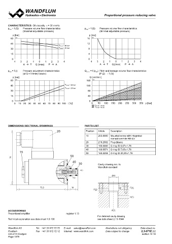
       CHARACTERISTICS  Oil viscosity  ν = 30 mm /s                                                                                Proportional pressure reducing cartridge
                                         2
       p  = f (Q)   Pressure volume flow characteristics    p  = f (Q)   Pressure volume flow characteristics                       ◆  pilot operated                                   7 ⁄8 “-14 UNF
                                                             red
        red
                 (Maximal adjustable pressure)                        (Minimal adjustable pressure)                                 ◆  Q  = 60 l/min                                    Wandfluh standard
                                                                                                                                       max
          p [bar]                                              p [bar]                                                              ◆  p  = 400 bar
                                                                                                                                       max
        60  K0970                                            16  K0971                                                              ◆  p    = 350 bar
                                                                                                                                       N red max

        45                                                   12
                                          P N red = 48 bar
        30                                P N red = 25 bar    8
                                                                                                                                   DESCRIPTION                                          APPLICATION
        15                                                    4                                                                    Pilot  operated  proportional  pressure  reducing  valve  in  screw-in   The electrical remote control in conjunction with process controls
                                                                                                                                   cartridge construction for cavity according to Wandfluh standard.   allows  economical  solutions  with  repeatable  processes.  The
         0                                                    0
           4   3   2    1   0   1   2    3   4                  4   3   2    1   0   1   2    3   4                                Proportionally to the solenoid current, the solenoid force and the   screw-in cartridge is perfectly suitable for installation in control
                 A     T  Q [l/min]  P   A                          A     T  Q [l/min]  P   A                                  pressure in port A (1) rise. The valve functions practically indepen-  blocks. For machining the cartridge cavity in steel and aluminum
                                                                                                                                   dently of the pressure in port P (2). Pressure increase in the consu-  blocks, cavity tools are available (hire or purchase). Please refer to
          = f (l)   Pressure adjustment characteristics     Q   = f (p )  Pilot- and leakage volume flow characteristice


       p red                                                 st + L  red                                                           mer port A (1) to above the adjusted value, e.g. through an active   the data sheets in register 2.13.
                 [at Q = 0 l/min] / (static)                          [P (2) → T (3)]                                              consumer, is avoided by discharging excess oil to the tank T (3).
          p [bar]                                              Q [cm /min]                                                         With the solenoid deenergised, the oil flows freely from port P (2) to
                                                                   3
        60  K0972                                            160  K0973
                                                                                                                                   consumer port A (1). For the control, Wandfluh proportional ampli -
        45                                    P N red = 48 bar  120                                                                fiers are available (see register 1.13).
                                              P N red = 25 bar
        30                                                    80
        15                                                    40
         0                                                     0
           0   10  20  30  40 50 60 70 80 90  100 l [%]         0    50  100  150  200  250  300  350 p [bar]
                 A     T  Q [l/min]  P   A                       P N red = 25 bar
                                                                   P N red = 48 bar
                                                                                                                                   SYMBOL                                               ACTUATION
                                                                                                                                                                                         Actuation          Proportional solenoid, wet pin push
                                                                                                                                           (A) 1                                                            type, pressure tight
                                                                                                                                                                                         Execution          W.S37 / 19 x 50 (Data sheet 1.1-173)
       DIMENSIONS / SECTIONAL DRAWINGS                      PARTS LIST                                                                                                                                      M.S35 / 19 x 50 (Data sheet 1.1-174)
                                                                                                                                                                                         Connection         Connector socket EN 175301 – 803
                                        20                   Position  Article  Description                                          (P) 2  (T) 3                                                           Connector socket AMP Junior-Timer
                                                             15      253.8000  Mounted screw with integrated                                                                                                Connector Deutsch DT04 – 2P
                                                                              manual override HB 4,5
                                                             20      219.2002  Plug (black)
                                                             30      160.0060  O-ring ID 6,07 x 1,78
                                                             40      160.0071  O-ring ID 7,65 x 1,78
               15                                            50      160.2204  O-ring ID 20,35 x 1,78
                                                  50
         74
                                                   40                                                                              STANDARDS                                            INSTALLATION NOTES
                                                       30            Cavity drawing acc. to
                                                T(3)                 Wandfluh standard                                              Cartridge cavity    Wandfluh standard                Mounting type      Screw-in cartridge  ⁄8 “-14 UNF
                                                                                                                                                                                                                          7
                                                         A(1)                                                                       Solenoids           DIN VDE 0580                     Mounting position  Any, preferably horizontal
                                                                              Ø 11                                                  Connection execution D  EN 175301 – 803              Tightening torque  M  = 60 Nm Screw-in cartridge
                                                                                                                                                                                                             D
                                                   P(2)
                                                                                                                                    Protection class    EN 60 529                                           M  = 5 Nm knurled nut
                                                                                                                                                                                                             D
                                                                                                                                    Contamination efficiency ISO 4406                                       M  = 9,5 Nm HB0
                                                                                                                                                                                                             D
                                                                                                                                                                                                            M  = 5,5 Nm HB4,5
                             70,3                  14                                      T(3)                                                                                                              D
                                                                  P(2)
                                                                                           A(1)

                           A(1)
       ACCESSORIES                                                            A(1)
       Proportional amplifier                  register 1.13
                                                                     For detailed cavity drawing
       Technical explanation see data sheet 1.0-100                  see data sheet 2.13-1044
                       P(2)  T(3)

       Wandfluh AG        Tel.  +41 33 672 72 72   E-mail:  sales@wandfluh.com   Illustrations not obligatory   Data sheet no.
       Postfach           Fax  +41 33 672 72 12   Internet:  www.wandfluh.com   Data subject to change   2.3-671E 2/2                                 www.wandfluh.com  Illustrations are not binding  Data subject to change  1/4  Edition: 19 19  2.3-672 E
       CH-3714 Frutigen                                                                            Edition 16 18
       Page 1076
   1071   1072   1073   1074   1075   1076   1077   1078   1079   1080   1081