
Page 1080 - Softbound_Edition_19_en
P. 1080
Proportional pressure reducing valve
Proportional pressure reducing valve Proportional pressure reducing valve
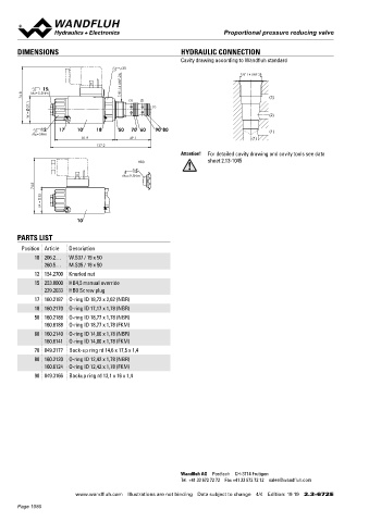
DIMENSIONS HYDRAULIC CONNECTION Proportional pressure reducing cartridge
Cavity drawing according to Wandfluh standard ◆ direct operated by means of pilot spool 7 ⁄8 “-14 UNF
s30 7/8"-14 UNF-2B ◆ Q = 20 l/min Wandfluh standard
max
p = 350 bar
◆
7/8"-14 UNF-2A ◆ p max = 200 bar
N red max
15
76.8 MD=5.5Nm (3) (2) (3)
37.1 (1)
W = (2) DESCRIPTION APPLICATION
Direct operated proportional pressure reducing valve with pilot These valves are used in hydraulic systems where the pressure has
12 17 10 18 50 70 60 90 80
MD=5Nm (1) spool actuation in screw-in cartridge construction for cavity to be changed frequently. The electrical remote control in conjunc-
81.9 49.1 (1) according Wandfluh standard. The proportional pressure reducing tion with process controls allows economical solutions with repea-
137.2 valve controls the pressure in port A (1). Proportionally to the sole- table processes. Direct operated pressure reducing valves are
Attention! For detailed cavity drawing and cavity tools see data noid current, the solenoid force and the pressure in port A (1) rise. used where a low minimal adjustable pressure is required. For
HB0 sheet 2.13-1045 The valve functions practically independently of the pressure in machining the cartridge cavity in steel and aluminum blocks, cavity
15 port P (2). Pressure increase in the consumer port A (1) to above the tools are available (hire or purchase). Please refer to the data
MD= 9.5Nm adjusted value, e.g. through an active consumer, is avoided by sheets in register 2.13.
74.8 discharging excess oil to the tank T (3). With the solenoid deenergi-
sed, the oil flows freely from consumer port A (1) to port T (3). For
35
the control, Wandfluh proportional amplifiers are available (see
M = register 1.13).
10
PARTS LIST
Position Article Description SYMBOL ACTUATION
10 206.2… W.S37 / 19 x 50 Actuation Proportional solenoid, wet pin push
260.5… M.S35 / 19 x 50 (A) 1 type, pressure tight
12 154.2700 Knurled nut Execution W.S37 / 19 x 50 (Data sheet 1.1-173)
15 253.8000 HB4,5 manual override M.S35 / 19 x 50 (Data sheet 1.1-174)
239.2033 HB0 Screw plug Connection Connector socket EN 175301 – 803
(P) 2 (T) 3 Connector socket AMP Junior-Timer
17 160.2187 O-ring ID 18,72 x 2,62 (NBR)
18 160.2170 O-ring ID 17,17 x 1,78 (NBR) Connector Deutsch DT04 – 2P
50 160.2188 O-ring ID 18,77 x 1,78 (NBR)
160.6188 O-ring ID 18,77 x 1,78 (FKM)
60 160.2140 O-ring ID 14,00 x 1,78 (NBR)
160.6141 O-ring ID 14,00 x 1,78 (FKM)
70 049.3177 Back-up ring rd 14,6 x 17,5 x 1,4
80 160.2120 O-ring ID 12,42 x 1,78 (NBR) STANDARDS INSTALLATION NOTES
160.6124 O-ring ID 12,42 x 1,78 (FKM)
Cartridge cavity Wandfluh standard Mounting type Screw-in cartridge ⁄8 “-14 UNF
7
90 049.3166 Backup ring rd 13,1 x 16 x 1,4
Solenoids DIN VDE 0580 Mounting position Any, preferably horizontal
Connection execution D EN 175301 – 803 Tightening torque M = 60 Nm Screw-in cartridge
D
Protection class EN 60 529 M = 5 Nm knurled nut
D
Contamination efficiency ISO 4406 M = 9,5 Nm HB0
D
M = 5,5 Nm HB4,5
D
Wandfluh AG Postfach CH-3714 Frutigen
Tel. +41 33 672 72 72 Fax +41 33 672 72 12 sales@wandfluh.com
www.wandfluh.com Illustrations are not binding Data subject to change 4/4 Edition: 19 19 2.3-672 E www.wandfluh.com Illustrations are not binding Data subject to change 1/4 Edition: 17 49 2.3-673 E
Page 1080