Page 1082 - Softbound_Edition_19_en
P. 1082

Proportional pressure reducing valve
                                                                         Proportional pressure reducing valve                                                                                          Proportional pressure reducing valve


       TYPE CODE                                                                                                                   PERFORMANCE SPECIFICATIONS
                                                                                                                                                    2
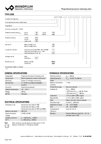
                                                                 M  P  P  PU10  -     -     /        -        #                    Oil viscosity u = 30 mm /s
       Pressure reducing valve                                                                                                      p =f (Q)  Pressure volume flow characteristic        p =f (Q)  Pressure volume flow characteristic
                                                                                                                                              Maximal adjustable pressure                          Minimal adjustable pressure
       Direct operated by means of pilot spool
                                                                                                                                       p [bar]                                              p [bar]
       Proportional                                                                                                                      K4167                                                K4168
                                                                                                                                      300                                                 100
                                                                                                                                                                                           90
       Screw-in cartridge 7/8“ - 14 UNF                                                                                               250                                                  80
                                                                                                                                      200                                   p N red  = 200 bar  70
                                                                                                                                                                                           60
       Nominal pressure range p N red    20 bar   20   115 bar   115                                                                  150                                                  50
                              80 bar       80      200 bar     200                                                                    100                                   p N red  = 115 bar  40
                                                                                                                                                                                           30
                                                                                                                                                                            p N red  = 80 bar
                                                                                                                                      50                                                   20
       Nominal voltage U      12 VDC       G12                                                                                                                              p N red  = 20 bar  10
                   N                                                                                                                   0                                                    0
                              24 VDC       G24                                                                                          25  20  15  10  5  0  5  10  15  20  25              25  20  15  10  5  0  5  10  15  20  25
                              without coil   X5                                                                                                A  T   Q [l/min]  P  A                             A  T   Q [l/min]  P  A

       Slip-on coil           Metal housing round              W
                              Metal housing square             M
       Connection execution   Connector socket EN 175301 - 803 / ISO 4400   D                                                       p =f (I)  Pressure adjustment characteristics
                              Connector socket AMP Junior - Timer    J                                                                        Bis I  = 40 % leicht erhöhte Hysterese
                              Connector Deutsch DT04 - 2P      G                                                                                  G
                                                                                                                                       p  [bar]
                                                                                                                                        red
       Sealing material       NBR                                                                                                     200  K4169                           p N red  = 200 bar
                              FKM (Viton)   D1                                                                                        180
                                                                                                                                      160
       Manual override        Manual override                 HB4,5                                                                   140                                  p N red  = 115 bar
                                                                                                                                      120
                              Screw plug                       HB0                                                                    100
                                                                                                                                      80                                   p N red  = 80 bar
                                                                                                                                      60
       Design index (subject to change)                                                                                               40
                                                                                                                                      20                                   p N red  = 20 bar
       2.3-673                                                                                                                         0
                                                                                                                                        0   10  20  30  40  50  60  70  80  90  100  I [%]
       GENERAL SPECIFICATIONS                              HYDRAULIC SPECIFICATIONS
       Designation        Proportional pressure reducing valve  Working pressure  p  = 350 bar
                                                                                max
       Construction       Direct operated by means of pilot spool  Nominal pressure   P N red  = 20, 80, 115, 200 bar
       Mounting           Screw-in cartridge construction   range                                                                  ACCESSORIES                                          MANUAL OVERRIDE
       Nominal size       7 ⁄8 “-14 UNF according to Wandfluh   Minimum adjustable   < 1 bar                                        Proportional amplifier           Register 1.13      HB4,5
                          standard                          pressure                                                                Electric plug B (black)          Article no. 219.2002  Optionally: Screw plug (HB0), no actuation possible
       Actuation          Proportional solenoid             Volume flow range  See characteristic                                   Technical explanations           Data sheet 1.0-100
       Ambient temperature  -25…+70 °C                      Leakage oil        at p  = 350 bar                                      Hydraulic fluids                 Data sheet 1.0-50
                                                                                  sys
       Weight             0,55 kg                                              < 30 ml/min for p N red  = 20, 80, 115 bar
       MTTFd              150 years                                            < 50 ml/min for p N red  = 200 bar                   Filtration                       Data sheet 1.0-50
                                                            Hysteresis         ≤ 4 % at optimal dither signal
                                                            Repeatability      ≤ 1 % at optimal dither signal
                                                            Fluid              Mineral oil, other fluid on request
       ELECTRICAL SPECIFICATIONS                            Viscosity range    12 mm /s…320 mm /s                                  SURFACE TREATMENT                                    SEALING MATERIAL
                                                                                   2
                                                                                            2
                                                                                                                                                                                        NBR or FKM (Viton) as standard, choice in the type code
                                                                                                                                      The cartridge body, the slip-on coil and the armature tube are
       Protection class   Connection execution D: IP65      Temperature range   -25…+70 °C (NBR)                                    ◆  zinc-nickel coated
                          Connection execution J: IP66      fluid              -20…+70 °C (FKM)
                          Connection execution G: IP67 and IP69K  Contamination   Class 18 / 16 / 13
       Relative duty factor  100 % DF                       efficiency
       Standard nominal   12 VDC, 24 VDC                    Filtration         Required filtration grade ß 6…10 ≥ 75,
       voltage                                                                 see data sheet 1.0-50
       Limiting current at  I  = 1360 mA (U  = 12VDC)
                                     N
                           G
       50 °C              I  = 680 mA (U  = 24VDC)
                           G
                                    N
       Note!   Other electrical specifications see data sheet 1.1-173
               (slip-on coil W) and 1.1-174 (slip-on coil M)


                         www.wandfluh.com  Illustrations are not binding  Data subject to change  2/4  Edition: 17 49  2.3-673 E                      www.wandfluh.com  Illustrations are not binding  Data subject to change  3/4  Edition: 17 49  2.3-673 E
       Page 1082
   1077   1078   1079   1080   1081   1082   1083   1084   1085   1086   1087