
Page 338 - Softbound_Edition_19_en
P. 338
Spool valve
Spool valve Spool valve
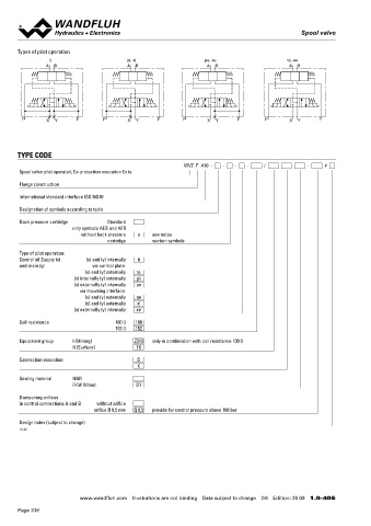
Types of pilot operation GENERAL SPECIFICATIONS ACTUATION
ti pi, xi pe, xe te, ae Designation 4/2-, 4/3-spool valve Solenoid spool valve direct operated
A B A B A B A B Data sheet 1.3-28
Mounting Flange construction
Nominal size NG10 according to ISO 4401-05 WDZFA04-AB1 / AB2 for 4/2-way AB1 / AB2
WDZFA04-AD1 / DB2 for other 4/2-way
Ambient temperature -25…+45 °C (operation as T6) WDZFA04-ADB for 4/3-way with spring centred mid position
-25…+60 °C (operation as T1…T5) WDZFA04-ADB for 4/2-way impulse execution detented
Weight 5,4 kg (1 K-solenoid)
a b a b a b a b
7,6 kg (2 K-solenoids)
P X Y T P X Y T P X Y T P X Y T MTTFd 150 years
TYPE CODE
WVZ F A10 - - - - / - #
Spool valve pilot operated, Ex-protection execution Ex ia HYDRAULIC SPECIFICATIONS ELECTRICAL SPECIFICATIONS
Working pressure p = 350 bar Protection class IP65
Flange construction max
Tank pressure p T max = 160 bar (type of pilot operation Relative duty factor Continuous operation
International standard interface ISO NG10 te, pi, ae and xi) Switching frequency 1'800 / h
p = 100 bar (type of pilot operation ti, Service life time 10 (number of switching cycles,
7
T max
Designation of symbols according to table pe and xe) theoretically)
Back pressure cartridge Standard Pilot pressure p v min : 8…14 bar, see performance limits Voltage tolerance ± 10 % with regard to nominal voltage
only symbols AEB and AFB p v max = 350 bar for connection X (control Limiting current at I = 90 mA (100 Ω execuiton)
min
without back pressure o see notes plate) 50 °C I = 64 mA (152 Ω execuiton)
cartridge section symbols p v max = 200 bar for connection X Temperature class T1…T6
min
(mounting interface)
Type of pilot operation: Coil resistance 100 Ω, 152 Ω
Control oil Supply (x) (x) and (y) internally ti Pressure pilot oil drain minimum lower by p v min Minimum power P = 0,81 W (100 Ω execution)
and drain (y) via control plate: Maximum volume flow Q = 160 l/min min
max
(x) and (y) externally te Leakage oil See characteristic and pilot valves consumption P = 0,62 W (152 Ω execution)
min
(x) internally (y) externally pi Note! Other electrical specifications, recommended power
(x) externally (y) internally pe Fluid Mineral oil, other fluid on request supply and safety-related limits see data sheet 1.1-185
via mounting interface: Viscosity range 12 mm /s…320 mm /s
2
2
(x) and (y) externally ae Temperature range -25…+45 °C (operation as T6, NBR)
(x) and (y) externally xi
(x) externally (y) internally xe fluid -20…+45 °C (operation as T6, FKM)
-25…+60 °C (operation as T1…T5, NBR)
Coil resistance 100 Ω 100 -20…+60 °C (operation as T1…T5, FKM)
152 Ω 152 Contamination Class 20 / 18 / 14
efficiency
Equipment group I (Mining) Z319 only in combination with coil resistance 100 Ω
II (Surface) T6 Filtration Required filtration grade ß 10…16 ≥ 75,
see data sheet 1.0-50
Connection execution D
K
Sealing material NBR
FKM (Viton) D1
Dampening orifices
in control connections A and B without orifice MANUAL OVERRIDE CERTIFICATES
orifice Ø 0,5 mm Q 0,5 provide for control pressure above 100 bar
HB4,5 as standard Surface Mining
Design index (subject to change) gas and dust
1.9-40
ATEX x x
IECEx x x
The certificates can be found on www.wandfluh.com
www.wandfluh.com Illustrations are not binding Data subject to change 2/6 Edition: 20 09 1.9-40 E www.wandfluh.com Illustrations are not binding Data subject to change 3/6 Edition: 20 09 1.9-40 E
Page 338