
Page 334 - Softbound_Edition_19_en
P. 334
WVYFA10
Spool valve WVYFA10
PERFORMANCE SPECIFICATIONS DIMENSIONS
Oil viscosity u = 30 mm /s 4/3-way spool valve (spring centring)
2
4/2-way spool valve (impulse)
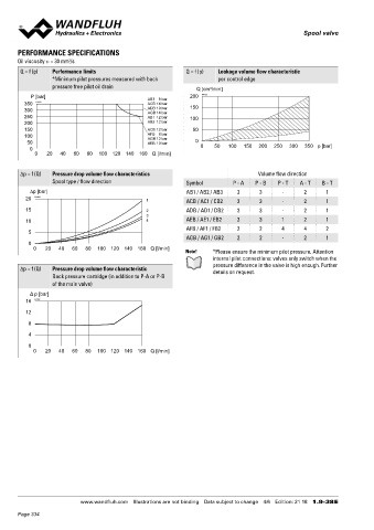
Q = f (p) Performance limits Q = f (p) Leakage volume flow characteristic
*Minimum pilot pressures measured with back per control edge 237
pressure free pilot oil drain Q [cm /min] 57 45
3
P [bar] AB3 8 bar 200 K4123
350 K4122 ACB 14 bar
300 ADB 10 bar 150
AGB 14 bar
250 AB1 12 bar 100
200 AB2 12 bar 20
150 ACB 12 bar 50
100 AFB 8 bar
AGB 12 bar
50 AEB 10 bar 0
0 0 50 100 150 200 250 300 350 p [bar] a b
0 20 40 60 80 100 120 140 160 Q [l/min] 190.9
80 Y=G1/8" X=G1/8" 20
70
∆p = f (Q) Pressure drop volume flow characteristics Volume flow direction 90*
Spool type / flow direction Symbol P - A P - B P - T A - T B - T 60
∆p [bar] AB1 / AB2 / AB3 3 3 - 2 1 35
20 K4124 1 ACB / AC1 / CB2 3 3 - 2 1 69.6
15 2 ADB / AD1 / DB2 3 3 - 2 1 29
3
10 4 AEB / AE1 / EB2 3 3 1 2 1
AFB / AF1 / FB2 2 2 4 4 2 10 40 30 6.5 68
5 10.5
AGB / AG1 / GB2 2 2 - 2 1 20 93
0
0 20 40 60 80 100 120 140 160 Q [l/min] 133
Note! *Please ensure the minimum pilot pressure. Attention * Pos.90 Control plate with type of pilot operation te, pi, pe only
internal pilot connections: valves only switch when the
pressure difference in the valve is high enough. Further 4/2-way spool valve (spring reset)
∆p = f (Q) Pressure drop volume flow characteristic details on request.
Back pressure cartridge (in addition to P-A or P-B 155.4
of the main valve)
Δ p [bar]
16 K4132
12
8
4
a 170.9
0
0 20 40 60 80 100 120 140 160 Q [l/min] 12
185.4
www.wandfluh.com Illustrations are not binding Data subject to change 4/6 Edition: 21 18 1.9-38 E www.wandfluh.com Illustrations are not binding Data subject to change 5/6 Edition: 21 18 1.9-38 E
Page 334