
Page 331 - Softbound_Edition_19_en
P. 331
WVYFA10
Spool valve
Spool valve
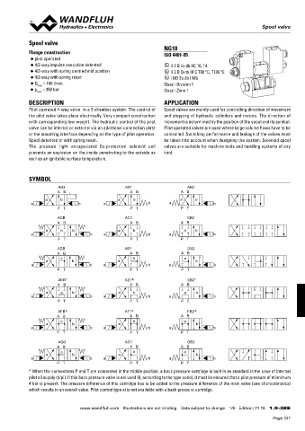
NG10
Flange construction ISO 4401-05
◆ pilot operated
◆ 4/2-way impulse execution detented x II 2 G Ex db IIC T6, T4
◆ 4/3-way with spring centred mid position x II 2 D Ex tb III C T80 °C, T130 °C
◆ 4/2-way with spring reset x I M2 Ex db I Mb
◆ Q = 160 l/min Class I Division 1
max
◆ p = 350 bar Class I Zone 1
max
DESCRIPTION APPLICATION
Pilot operated 4-way valve in a 5 chamber system. The control of Spool valves are mainly used for controlling direction of movement
the pilot valve takes place electrically. Very compact construction and stopping of hydraulic cylinders and motors. The direction of
with corresponding low weight. The hydraulic control of the pilot movement is determined by the position of the spool and its symbol.
valve can be internal or external via an additional connection plate Pilot operated valves are used where large volume flows have to be
or the mounting interface depending on the type of pilot operation. controlled. Switching performance and leakage of the valves must
Spool detented or with spring reset. be taken into account when designing the system. Solenoid spool
The pressure tight encapsulated Ex-protection solenoid coil valves are suitable for machine tools and handling systems of any
prevents an explosion on the inside penetrating to the outside as kind.
well as an ignitable surface temperature.
SYMBOL
AB3 AB1 AB2
A B A B A B
a b a b a b
a b a b a b
P T P T P T
ACB AC1 CB2
A B A B A B
a o b a b a b
a b a b a b
P T P T P T
ADB AD1 DB2
A B A B A B
o b a
a b a b
a b a b a b
P T P T P T
AEB* AE1 * EB2*
A B A B A B
a o b a b a b
a b a b a b
P T P T P T
AFB * AF1 * FB2 *
A B A B A B
o b a
a b a b
a b a b a b
P T P T P T
AGB AG1 GB2
A B A B A B
o b a
a b a b
a b a b a b
P T P T P T
* When the connections P and T are connected in the middle position, a back pressure cartridge is built in as standard in the case of internal
pilot oil supply (ti/pi). If this back pressure valve is not used (0, according to the type code), it must be ensured that a pilot pressure of minnimum
4 bar is present. The pressure difference of this cartridge has to be added to the pressure difference of the main valve (see characteristics)
which results in an overall value. Pilot control type xi is not available with a back pressure cartridge.
www.wandfluh.com Illustrations are not binding Data subject to change 1/6 Edition: 21 18 1.9-38 E
Page 331