
Page 326 - Softbound_Edition_19_en
P. 326
Spool valve
Spool valve Spool valve
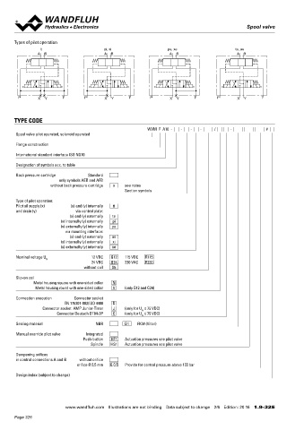
Types of pilot operation GENERAL SPECIFICATIONS ACTUATION
ti pi, xi pe, xe te, ae Designation 4/2-, 4/3-spool valve Solenoid spool valve direct operated
A B A B A B A B Data sheet 1.2-33 (slip-on coil)
Mounting Flange construction
Nominal size NG10 according to ISO 4401-05 WDMFA04-AB1 / AB2 for 4/2-way AB1 / AB2
WDMFA04-AD1 / DB2 for other 4/2-way
Actuation Electrical WDMFA04-ADB for 4/3-way with spring centred mid position
Ambient temperature -25…+70 °C WDMFA04-ADB for 4/2-way impulse execution detented
if > +50 °C, then no undervoltage is
a b a b a b a b
admissible
P X Y T P X Y T P X Y T P X Y T Weight 3,5 kg (1 solenoid)
3,8 kg (2 solenoids)
0,3 kg control plate
MTTFd 150 years
TYPE CODE
WVM F A10 - - - - / - #
Spool valve pilot operated, solenoid operated
HYDRAULIC SPECIFICATIONS INSTALLATION NOTES
Flange construction
Working pressure p = 350 bar Mounting type Flange mounting
max
International standard interface ISO NG10 Tank pressure p T max = 160 bar (type of pilot operation 4 fixing holes for
te, pi, ae and xi) socket head screws M6 x 40
Designation of symbols acc. to table p T max = 100 bar (type of pilot operation ti, Mounting position Any, preferably horizontal
pe and xe) Tightening torque M = 13.5 Nm ± 10 %, quality min. 10.9
Back pressure cartridge Standard D
only symbols AEB and AFB Pilot pressure p v min : 8…14 bar, see performance limits
without back pressure cartridge o see notes p v max = 350 bar for connection X (control M = 10.5 Nm ± 10 %, quality 8.8:
D
Section symbols plate)
p = 200 bar for connection X ◆ maximum tank pressure without
v max
Type of pilot operation: (mounting interface) external connections: 80 bar
Pilot oil supply (x) (x) and (y) internally ti
and drain (y) via control plate: Pressure pilot oil drain minimum lower by p v min ◆ maximum tank pressure and
(x) and (y) externally te Maximum volume flow Q = 160 l/min maximum pressure external
max
(x) internally (y) externally pi Leakage oil See characteristic and pilot valves connections: 35 bar
(x) externally (y) internally pe
via mounting interface: Fluid Mineral oil, other fluid on request Note! The length of the fixing screw depends on the base
(x) and (y) externally ae Viscosity range 12 mm /s…320 mm /s material of the connection element.
2
2
(x) internally (y) externally xi Temperature range -25…+70 °C (NBR)
(x) externally (y) internally xe
fluid -20…+70 °C (FKM)
Nominal voltage U N 12 VDC G12 115 VDC R115 Contamination Class 20 / 18 / 14
24 VDC G24 230 VAC R230 efficiency
without coil X5
Filtration Required filtration grade ß 10…16 ≥ 75,
Slip-on coil see data sheet 1.0-50
Metal housing square with one-sided collar N
Metal housing round with one-sided collar V (only G12 and G24)
Connection execution Connector socket
EN 175301-803/ISO 4400 D
Connector socket AMP Junior-Timer J (only for U ≤ 75 VDC)
N
Connector Deutsch DT04-2P G (only for U ≤ 75 VDC)
N SURFACE TREATMENT SEALING MATERIAL
Sealing material NBR D1 FKM (Viton) ◆ The main valve body, the distance plate, the screw plugs, the NBR or FKM (Viton) as standard, choice in the type code
slip-on coil and the armature tube are zinc-nickel coated
Manual override pilot valve Integrated ◆ The pilot valve body is coated with a two component paint
Push-button HF1 Actuation pressures see pilot valve
Spindle HS1 Actuation pressures see pilot valve
Dampening orifices
in control connections A and B without orifice
orifice Ø 0,5 mm Q 0,5 Provide for control pressure above 100 bar
Design index (subject to change)
www.wandfluh.com Illustrations are not binding Data subject to change 2/6 Edition: 20 16 1.9-32 E www.wandfluh.com Illustrations are not binding Data subject to change 3/6 Edition: 20 16 1.9-32 E
Page 326