Page 322 - Softbound_Edition_19_en
P. 322

Spool valve
                                                                                                  Spool valve                                                                                                                 Spool valve


       GENERAL SPECIFICATIONS                              HYDRAULIC SPECIFICATIONS                                                MANUAL OVERRIDE                                      ACCESSORIES
       Designation        4/2-spool valve                   Working pressure   p  = 315 bar                                        Integrated in the cover. Actuation by pressing the pin.  Fixing screws            Data sheet 1.0-60
                                                                                max
       Construction       Direct operated                   Tank pressure      p   = 160 bar                                                                                             Threaded subplates          Data sheet 2.9-40
                                                                                T max
       Mounting           Flange construction               System pressure    25…315 bar                                                                                                Multi-station subplates     Data sheet 2.9-70
       Nominal size       NG10 according to ISO 4401-05     Reversal pressure  Maximum 90% of the system pressure                                                                        Horizontal mounting blocks  Data sheet 2.9-110
       Actuation          Integral pressure reversal        Maximum volume flow  Q  = 60 l/min, see characteristics
                                                                                max                                                                                                      Technical explanations      Data sheet 1.0-100
       Ambient temperature  -25…+70 °C                      Minimum volume flow  Q  = 4 l/min
                                                                                min                                                                                                      Filtration                  Data sheet 1.0-50
       Weight             4,8 kg                            Fluid              Mineral oil, other fluid on request
       MTTFd              150 years                         Viscosity range    12 mm /s…320 mm /s
                                                                                   2
                                                                                            2
                                                            Temperature range   -25…+70 °C (NBR)
                                                            fluid              -20…+70 °C (FKM)
                                                            Contamination      Class 20 / 18 / 14
                                                            efficiency
                                                            Filtration         Required filtration grade ß 10…16 ≥ 75,             SEALING MATERIAL                                     COMMISSIONING
                                                                               see data sheet 1.0-50                               NBR or FKM (Viton) as standard, choice in the type code  Attention!    The reversal pressure adjusted on the pressure reliefs
                                                                                                                                                                                                 must not exceed a maximum of 90% of the system
                                                                                                                                                                                                 pressure.


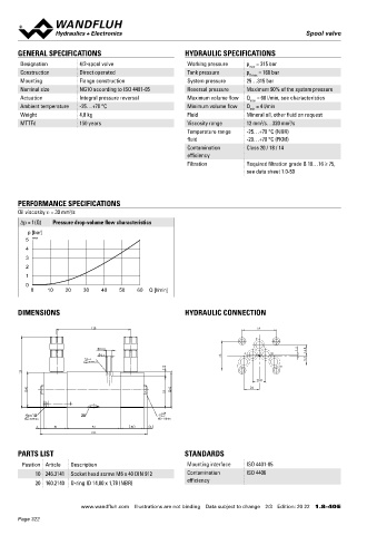
       PERFORMANCE SPECIFICATIONS
                       2
       Oil viscosity u = 30 mm /s
       Δp = f (Q)  Pressure drop-volume flow characteristics
          p [bar]                                                                                                                  INSTALLATION NOTES                                   SURFACE TREATMENT
         5  K0435                                                                                                                                                                          The valve body is coated with a two component paint
                                                                                                                                    Mounting type      Flange mounting                   ◆
         4                                                                                                                                                                                 The covers and the screws are zinc coated
                                                                                                                                                       4 fixing holes for                ◆
         3                                                                                                                                             socket head screws M6 x 65
         2                                                                                                                          Mounting position  Any, preferably horizontal
         1                                                                                                                          Tightening torque  Fixing screws M  = 8,9 Nm (quality 8.8,
                                                                                                                                                                   D
         0                                                                                                                                             zinc coated)
           0    10    20   30    40    50   60  Q [l/min]
                                                                                                                                   Note!    The length of the fixing screw depends on the base
                                                                                                                                            material of the connection element.
       DIMENSIONS                                          HYDRAULIC CONNECTION

                               128                                                 54
                                                                                  P


                                  10.5                                                          1.5
                                                                                                   16.8
                                   6.5                                  46    A        B
                           MD=8.9Nm                                                                9.7
                                                                            T            To
                                                      7
         123
                                                                                   20.8
          60                                           62                        24
                                                      55

           10              20                       s14
         MD= 8.9Nm                                 MD= 10Nm
             6     40          93          40    6
                               185

       PARTS LIST                                          STANDARDS

        Position Article  Description                       Mounting interface  ISO 4401-05
            10 246.3141  Socket head screw M6 x 40 DIN 912  Contamination      ISO 4406
            20 160.2140  O-ring ID 14,00 x 1,78 (NBR)       efficiency                                                                                                                  Wandfluh AG  Postfach  CH-3714 Frutigen
                                                                                                                                                                                        Tel. +41 33 672 72 72  Fax +41 33 672 72 12  sales@wandfluh.com

                           www.wandfluh.com  Illustrations are not binding  Data subject to change  2/3  Edition: 20 22  1.8-40 E                      www.wandfluh.com  Illustrations are not binding  Data subject to change  3/3  Edition: 20 22  1.8-40 E
       Page 322
   317   318   319   320   321   322   323   324   325   326   327