
Page 342 - Softbound_Edition_19_en
P. 342
Over-view
Spool valve
Spool valve Proportional spool valves
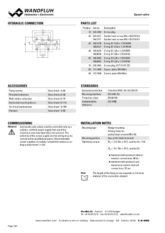
HYDRAULIC CONNECTION PARTS LIST
Position Article Description NG3-Mini NG4-Mini NG6 ISO NG10 ISO
93
70.8 10 239.7203 Screw plug
54 Type designation
20 246.2151 Socket head screw M5 x 50 DIN 912
P 246.2171 Socket head screw M5 x 70 DIN 912 WDPFA03-ACB WDPFA04-ACB WDPFA06-ACB WDPFA10-ACB
X A B Y 1.10-66 1.10-73 1.10-77 1.10-3400
68 12 T To 1.5 16.8 46 30 160.2120 O-ring ID 12,42 x 1,78 (NBR)
9.7 160.8124 O-ring ID 12,42 x 1,78 (FKM) WDPFA04-ACB-../NE WDBFA06-ACB
40 160.2076 O-ring ID 7,65 x 1,78 (NBR) 1.10-3240 1.10-88
160.8076 O-ring ID 7,65 x 1,78 (FKM) (integrated electronics) (Ex d)
20.8
48 60 160.2052 O-ring ID 5,28 x 1,78 (NBR) WDPFA06-ACB-../ME
160.6052 O-ring ID 5,28 x 1,78 (FKM) 1.10-3340
70 238.1405 Screw plug VSTI G1/8"-ED (integrated electronics)
80 173.1400 Spacer plate NG4 Mini WDRFA06-ACB
90 173.1500 Control plate NG4 Mini 1.10-82
(integr. electr. and LVDT)
BRW.4D41
1.10-70
ACCESSORIES STANDARDS (integr. electr. and LVDT)
Fixing screws Data sheet 1.0-60 Explosion protection Directive 2014 / 34 / EU (ATEX) VWS4D41 VWS4D61 VWS4D101
Threaded subplates Data sheet 2.9-40 Mounting interface ISO 4401-05 1.10-06 1.10-11 1.10-20
Multi-station subplates Data sheet 2.9-70 Protection class EN 60 529 WDPFA03-AC1 WDPFA04-AC1 WDPFA06-AC1 WDPFA10-AC1
1.10-77
1.10-3400
1.10-73
Horizontal mounting blocks Data sheet 2.9-110 Contamination ISO 4406 1.10-66
efficiency WDPFA04-AC1-../NE
Technical explanations Data sheet 1.0-100 1.10-3240
Filtration Data sheet 1.0-50 (integrated electronics)
WDPFA03-CB2 WDPFA04-CB2 WDPFA06-CB2 WDPFA10-CB2
1.10-66 1.10-73 1.10-77 1.10-3400
COMMISSIONING INSTALLATION NOTES WDPFA04-CB2-../NE
Attention! Intrinsically safe valves must be controlled only by a Mounting type Flange mounting 1.10-3240
suitable, certified power supply from out of the (integrated electronics)
hazardous area (see Operating Instructions). The 4 fixing holes for
selection of the power supply and the wiring must be socket head screws M6 x 40
carried out by qualified personnel. Recommended Mounting position Any, preferably horizontal
power supplies and safety-related limit values accor- Tightening torque M = 13.5 Nm ± 10 %, quality min. 10.9
D
ding to data sheet 1.1-185
M = 10.5 Nm ± 10 %, quality 8.8:
D
◆ maximum tank pressure without
external connections: 80 bar
◆ maximum tank pressure and
maximum pressure external
connections: 35 bar
Note! The length of the fixing screw depends on the base
material of the connection element.
Wandfluh AG Postfach CH-3714 Frutigen
Tel. +41 33 672 72 72 Fax +41 33 672 72 12 sales@wandfluh.com
Wandfluh AG Tel. +41 33 672 72 72 E-mail: sales@wandfluh.com Illustrations not obligatory Data sheet no.
www.wandfluh.com Illustrations are not binding Data subject to change 6/6 Edition: 20 09 1.9-40 E Postfach Fax +41 33 672 72 12 Internet: www.wandfluh.com Data subject to change 1.10-04E 1/2
CH-3714 Frutigen Edition 21 17
Page 342