
Page 749 - Softbound_Edition_19_en
P. 749
Digital controller modul
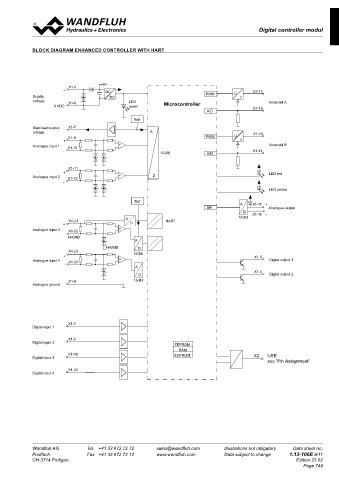
Digital controller module SD7
BLOCK DIAGRAM ENHANCED CONTROLLER WITH HART
X1-5
+ DC X1-15
Supply DC PWM U I
voltage X1-6 LED Solenoid A
0 VDC green Microcontroller X1-16
A/D
Ref
Stabilised output X1-7
voltage A X1-13
X1-9 PWM U
+ I
Analogue input 1 X1-10 + - Solenoid B
- 10-Bit A/D X1-14
X1-11
+ LED red
Analogue input 2 X1-12 + - D
-
LED yellow
Ref
A X1-17 +
SPI Analogue output
D X1-18 -
A 12-Bit
X1-21 HART
+ H
Analogue input 3 X1-22 + -
-
H-GND
A
H-GND D
X1-23
+ 16-Bit X1-3
Analogue input 4 X1-24 + - Digital output 1
-
A
X1-4
D Digital output 2
X1-8 16-Bit
Analogue ground
X1-1
Digital input 1
X1-2
Digital input 2
FEPROM
RAM
X1-19 EEPROM X2 USB
Digital input 3
see "Pin Assignment"
X1-20
Digital input 4
Wandfluh AG Tel. +41 33 672 72 72 sales@wandfluh.com Illustrations not obligatory Data sheet no.
Postfach Fax +41 33 672 72 12 www.wandfluh.com Data subject to change 1.13-106E 9/11
CH-3714 Frutigen Edition 23 02
Page 749