
Page 743 - Softbound_Edition_19_en
P. 743
Digital controller module SD7
Digital controller modul
ELECTRICAL SPECIFICATIONS
Protection class IP 30 according to EN 60 529 Fieldbus (option)
Supply voltage 24 VDC or 12 VDC
Voltage range: • Device receptacle DSUB, 9-pole, CANopen, J1939, Profibus
• 24 VDC 21…30 V • Screw terminals HART
• 12 VDC 10,5…15 V • Bus topology Line, differential signal transmission
Residual ripple <10 % • Potential separation 500 VDC
Fuse Low
Current consumption:
• No-load current approx. 40 mA Solenoid current:
• Maximum current • Minimal current I Adjustable 0…950 mA
min
consumption No-load current + 1,8 A Factory setting 150 mA
per solenoid (with 24 VDC) • Maximal current I max Adjustable I min …1,8 A (with 24 VDC)
Consumption no-load current + 2,3 A I min …2,3 A (with 12 VDC)
per solenoid (with 12 VDC) Factory setting 700 mA
Command value signal: Selectable by means of software • Accumulated current
Input 1 and 2 and 4 (option): limitation The accumulated current of the simulta-
Differential input not galvanically separated, neously controlled solenoids depends on the
for ground potential difference up to 1,5 V ambient temperature. Further information can
4…+20 mA / 0…+20 mA be found in the Operating instructions.
0…+10 V (1- or 2-solenoid version) Dither Frequency adjustable 2…500 Hz
-10…+10 V (2-solenoid version only) Factory setting 100 Hz
Input 3 (option): Level adjustable 0…400 mA
Galvanically separated for HART signal Factory setting 100 mA
Resolution 10-bit (for analog inputs 1 and 2) Temperature drift <1 % at ΔT = 40 °C
16-bit (for analog inputs 3 and 4) Digital inputs Switching threshold high 6…30 VDC
Input resistance Voltage input >18 kΩ Switching threshold low 0…1 VDC
Load for current input = 250 Ω Digital input 5 – 7 can be used as frequency
Measuring system input DSUB plug coupling 9-pole (female) to input (frequencies 0…5 kHz) and as PWM
front panel according to RS422 standard input (automatic frequency recognition)
selectable by software Digital outputs Low-Side-Switch:
- Absolutely via Start/Stop U max = 40 VDC
- Absolutely via SSI (1... 32 bit, gray or binary) I max = -700 mA
Analog output Enhanced controller: Ramps adjustable 0…500 s
Voltage output ± 10 VDC Serial interface USB (plug type B)
Max. output current ± 3 mA for parameterising with «PASO»
Enhanced controller with HART: EMV
Current output 0...20 mA Immunity EN 61 000-6-2
Max. output voltage 12 VDC Emission EN 61 000-6-4
Stabilised output 10 VDC (with 24 VDC)
voltage 8 VDC (with 12 VDC)
Max. load 30 mA
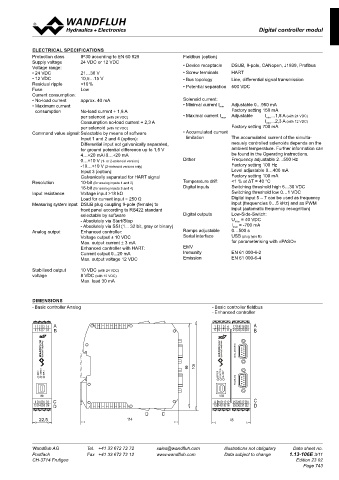
DIMENSIONS
- Basic controller Analog - Basic controller fieldbus
- Enhanced controller
A A B B A B
1 2 3
1 2
1 2 3 4 4 17 18 19 203 4 A A 1 2 3 4 17 18 19 20 A
5 6
5 6 7 8 8 21 22 23 247 8 B B 5 6 7 8 21 22 23 24 B
5 6 7
DIGITAL SENSOR X3 DIGITAL SENSOR X3
99 99 105 105 99 105
ERROR ERROR FUNCTION FUNCTION SUPPLY SUPPLY ERROR FUNCTION SUPPLY ERROR FUNCTION SUPPLY
FIELDBUS X4 FIELDBUS X4
USB USB USB
USB
9 10 11 12 25 26 27 28 11 12
9 10 11 12 9 10 C C 9 10 11 12 25 26 27 28 C
13 14 15 16
13 14 15 16 29 30 31 32 15 16 D D 13 14 15 16 29 30 31 32 D
13 14
D D C C D C
45 22,5 114 114 45 114
Wandfluh AG Tel. +41 33 672 72 72 sales@wandfluh.com Illustrations not obligatory Data sheet no.
Postfach Fax +41 33 672 72 12 www.wandfluh.com Data subject to change 1.13-106E 3/11
CH-3714 Frutigen Edition 23 02
Page 743
17 18 19 20
1 2 3 4 1 2 3 4 1 2 3 4 1 2 3 4 17 18 19 20
5
21 22 23 24
5 6 7 8 6 7 8 5 6 7 8 21 22 23 24
1 2 3 4
1 2 3 4 5 6 7 8 17 18 19 20 1 2 3 4 1 2 3 4 17 18 19 20
17 18 19 20 21 22 23 24 17 18 19 20 21 22 23 24
5 6 7 8 5 6 7 8 5 6 7 8 5 6 7 8
21 22 23 24 21 22 23 24
DIGITAL SENSOR X3 DIGITAL SENSOR X3
DIGITAL SENSOR X3 DIGITAL SENSOR X3 DIGITAL SENSOR X3 DIGITAL SENSOR X3
ERROR FUNCTION SUPPLY ERROR FUNCTION FIELDBUS X4 SUPPLY ERROR FUNCTION SUPPLY ERROR ERROR FUNCTION FUNCTION SUPPLY SUPPLY ERROR FUNCTION SUPPLY FIELDBUS X4 ERROR FUNCTION SUPPLY FUNCTION SUPPLY
FIELDBUS X4 FIELDBUS X4 FIELDBUS X4 ERROR FIELDBUS X4
USB
USB
USB 9 10 11 12 USB
13 14 15 16 USB USB USB USB
9 10 11 12 25 26 27 28 9 10 11 12 9 10 11 12 25 26 27 28
9 10 11 12 25 26 27 28
9 10 11 12 25 26 27 28
13 14 15 16 29 30 31 32 9 10 11 12 25 26 27 28 13 14 15 16 13 14 15 16 29 30 31 32 9 10 11 12 25 26 27 28 13 14 15 16 29 30 31 32
13 14 15 16 29 30 31 32
13 14 15 16 29 30 31 32
13 14 15 16 29 30 31 32