
Page 739 - Softbound_Edition_19_en
P. 739
Digital amplifier module SD7 Digital amplifier module SD7
Digital amplifier module
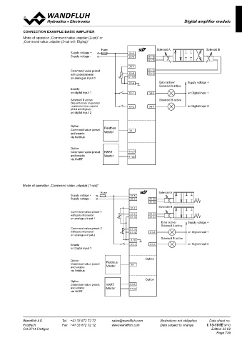
BLOCK DIAGRAM ENHANCED AMPLIFIER WITH HART CONNECTION EXAMPLE BASIC AMPLIFIER
Mode of operation „Command value unipolar (2-sol)“ or
„Command value unipolar (2-sol with DigInp)“
Fuse Solenoid A Solenoid B
Supply voltage +
X1-5 Supply voltage -
+ DC X1-15
Supply DC PWM U I
voltage X1-6 LED Solenoid A Fuse Solenoid A Solenoid B
Supply voltage +
0 VDC green Microcontroller Command value preset
Supply voltage -
A/D X1-16 with potentiometer
on analogue input 1
Ref
Error active/ Supply voltage +
Stabilised output X1-7 Command value preset Solenoid A active
with potentiometer
voltage A X1-13 Enable
on analogue input 1
X1-9 PWM U on digital input 1 on Digital input 1
+ I Error active/ Supply voltage +
Analogue input 1 X1-10 + - Solenoid B Solenoid B active Solenoid A active
Solenoid B active
Enable
- X1-14 Only with mode of operation
10-Bit A/D on digital input 1
on Digital input 2
«command value unipolar on Digital input 1
(2-Sol with DigInp)»
Solenoid B active
on digital input 2 Solenoid B active
X1-11 Only with mode of operation
+ LED red «command value unipolar on Digital input 2
Analogue input 2 X1-12 + - D (2-Sol with DigInp)»
on digital input 2
- Option
LED yellow Command value preset Fieldbus X4
Master
and enable
Option
Command value preset
Ref A X1-17 + via fieldbus Fieldbus X4
Master
SPI Analogue output and enable
via fieldbus
D X1-18 - Option
X1-21 A HART 12-Bit Command value preset HART X1-21
+ H and enable Master X1-22
Option
Command value preset
Analogue input 3 X1-22 + - via HART HART X1-21
- and enable Master
H-GND X1-22
A via HART
H-GND D
X1-23 16-Bit
+ X1-3
Analogue input 4 X1-24 + - Digital output 1
-
A Mode of operation „Command value unipolar (1-sol)“
X1-4 Fuse Solenoid A
D Digital output 2 Supply voltage + Fuse Solenoid A
X1-8 16-Bit Supply voltage -
Supply voltage +
Analogue ground Supply voltage -
Solenoid B
Solenoid B
Command value preset 1
Command value preset 1
with potentiometer
with potentiometer
on analogue input 1
on analogue input 1
Error active/ Supply voltage +
Supply voltage +
Error active/
Solenoid A active
X1-1 Solenoid A active
Digital input 1 Command value preset 2
Command value preset 2
with potentiometer
with potentiometer on Digital input 1
on Digital input 1
on analogue input 2
X1-2 on analogue input 2
Solenoid B active
Digital input 2 Solenoid B active
FEPROM
RAM Enable on Digital input 2
on Digital input 2
X1-19 EEPROM X2 USB Enable
on Digital input 1
Digital input 3 on Digital input 1
see "Pin Assignment"
X1-20 Option
Digital input 4 Option Fieldbus Option
Option X4
Command value preset
Master
and enable
Command value preset Fieldbus X4
via fieldbus
and enable Master
via fieldbus
Option
Option
Command value preset HART X1-21 Option
Option Master
and enable
X1-22
Command value preset HART X1-21
via HART
and enable Master X1-22
via HART
Wandfluh AG Tel. +41 33 672 72 72 sales@wandfluh.com Illustrations not obligatory Data sheet no. Wandfluh AG Tel. +41 33 672 72 72 sales@wandfluh.com Illustrations not obligatory Data sheet no.
Postfach Fax +41 33 672 72 12 www.wandfluh.com Data subject to change 1.13-101E 8/10 Postfach Fax +41 33 672 72 12 www.wandfluh.com Data subject to change 1.13-101E 9/10
CH-3714 Frutigen Edition 23 02 CH-3714 Frutigen Edition 23 02
Page 739