
Page 1155 - Softbound_Edition_19_en
P. 1155
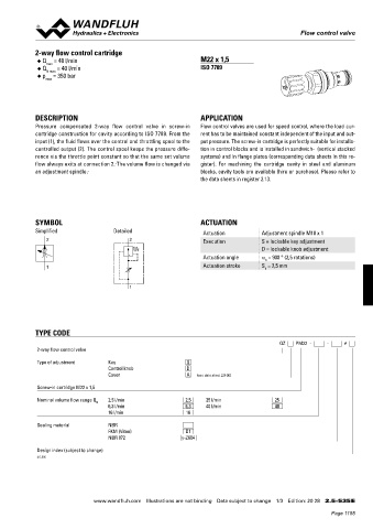
Flow control valves                                                                             Flow control valve
                                                                                                 Flow control valve

 CHARACTERISTICS Oil viscosity  υ = 30 mm /s  2-way flow control cartridge
 2
 Q = f (p)  Volume flow pressure characteristics  ∆p = f (Q)   Pressure drop characteristics for return flow  ◆  Q  = 48 l/min  M22 x 1,5
                max
       (from 2 → 1)   ◆  Q   = 40 l/min                          ISO 7789
                N max
 Q [l/min]  p[bar]  ◆  p  = 350 bar
 50  K0784  10  K0783  Q = 40 l/min  max
 N

 40  Q = 40 l/min  8
 N
 N
 30  Q = 25 l/min  6
 Q = 16 l/min
 N
 20  Q = 10 l/min  4  Q = 1 l/min
 N
 N
 Q = 6,3 l/min
 N
 10  Q = 4 l/min  2  DESCRIPTION                                 APPLICATION
 N
 Q = 1; 1,6;
 N
 0          2,5 l/min  0  Pressure  compensated  2-way  flow  control  valve  in  screw-in    Flow control valves are used for speed control, where the load cur-
 0  50  100  150  200  250  300  350 p [bar]  0  10  20  30  40  50  Q [l/min]  cartridge construction for cavity according to ISO 7789. From the   rent has to be maintained constant independent of the input and out-
            input (1), the fluid flows over the control and throttling spool to the   put pressure. The screw-in cartridge is perfectly suitable for installa-
            controlled output (2). The control spool keeps the pressure diffe-  tion in control blocks and is installed in sandwich-  (vertical stacked
 DIMENSIONS / SECTIONAL DRAWINGS  rence via the throttle point constant so that the same set volume   systems) and in flange plates (corresponding data sheets in this re-
            flow always exits at connection 2.  The volume flow is changed via   gister).  For  machining  the  cartridge  cavity  in  steel  and  aluminum
 Screw setting versions „S“

            an adjustment spindle.                               blocks, cavity tools are available (hire or purchase). Please refer to
 Cavity drawing according to

 Ø 17  ISO 7789–22–01–0–98                                       the data sheets in register 2.13.
 20
 s4  M22x1,5
 30
 s13
            SYMBOL                                               ACTUATION
 41  (2)    Simplified                Detailed                    Actuation          Adjustment spindle M10 x 1
 s27
                2                         2                       Execution          S = lockable key adjustment
 ø 30  (1)                                                                           D = lockable knob adjustment
 79
 40                                                               Actuation angle    a  = 900 ° (2,5 rotations)
                                                                                      b
 M22x1,5  (1)                                                     Actuation stroke   S  = 2,5 mm
                1                                                                     b
 38  For detailed cavity drawing
 and cavity tools see data
 60  sheet 2.13-1008.                      1
 50
            TYPE CODE
 PARTS LIST  ACCESSORIES                                                                  QZ     PM22  -     -     #
 Line mount body   Data sheet 2.9-205  2-way flow control valve
 Position   Article   Description
 20   193.1050   Retainer for shaft RD5 DIN 6799  Type of adjustment   Key   S
 30   153.1403   Hexagonal nut 0,5D M8       Control knob    D
                                                             A
                                    Cover
 40   160.2188   O-ring ID 18,77x1,78                           (see data sheet 2.0-50)
 50   160.2156   O-ring ID 15,60x1,78  Screw-in cartridge M22 x 1,5
 2
 1
 60   049.3196   Back-up ring RD 16,1x19x1,4
 1  2  Technical explanation see data sheet 1.0-100  Nominal volume flow range Q    2,5 l/min   2,5    25 l/min   25
                                N   6,3 l/min               6,3    40 l/min              40
                                    16 l/min                16
             Sealing material       NBR
                                    FKM (Viton)             D1
                                    NBR 872                y-Z604

             Design index (subject to change)
             2.5-535


 Wandfluh AG   Tel.  +41 33 672 72 72   E-mail:  sales@wandfluh.com   Illustrations not obligatory   Data sheet no.
 Postfach   Fax  +41 33 672 72 12   Internet:  www.wandfluh.com   Data subject to change   2.5-530E 2/2   www.wandfluh.com  Illustrations are not binding  Data subject to change  1/3  Edition: 20 28  2.5-535 E
 CH-3714 Frutigen                   Edition 05 06
                                                                                                           Page 1155