
Page 1153 - Softbound_Edition_19_en
P. 1153
Flow control valves Flow control valves
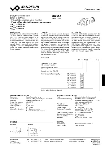
Flow control valve
CHARACTERISTICS Oil viscosity υ = 30 mm /s 2-way flow control valve M22x1,5
2
Q = f (p) Pressure drop-flow characteristics ∆p = f (Q) Pressure drop characteristics for return flow Screw-in cartridge ISO 7789
(from 2 → 1) • Integrated non-return valve function
Q [l/min] Q [l/min] • Fixed orifice, adjustable pressure compensator
20 K0015 25 K0016 Q N = 12,5 l/min Q N = 5 l/min • Q = 50 l/min
15 Q = 12,5 l/min 20 • Q max = 40 l/min
N N max
15 • p = 350 bar
10 Q N = 2 l/min max
Q = 5 l/min 10
N
5 Q = 2 l/min Q N = 1,25 l/min DESCRIPTION FUNCTION APPLICATION
N
Q = 1,25 l/min 5 Q N = 0,63 l/min 2-way flow control valve with non-return func- The 2-way flow control valve is designed For use in all hydraulic systems where the
N
0 Q = 0,63 l/min 0 tion as a screw-in cartridge with a thread to keep the speed of a consumer constant, supply volume flow has to be kept constant
N
0 50 100 150 200 250 300 350 p [bar] 0 50 100 150 200 250 300 350 p [bar] M22x1,5 for cavity according to ISO 7789. In irrespective of the load. The fixed measuring even when the load fluctuates. Installation of
its standard form, this flow control valve can orifice which is integrated into the pressure the screw-in cartridge in control blocks as well
be supplied with nine nominal volume flow compensating spool, determines the volume as in the Wandfluh sandwich plates (vertical
ranges. For a flow at low pressure drop in the flow. If there is a pressure change, the compen- stacked systems) and flange valves of the
opposite direction, a check function has been sating spool is displaced and changes the NG4-Mini and NG6 size. (Please note the se-
DIMENSIONS / SECTIONAL DRAWING integrated. The two part cartridge body is made outlet diameter in order to keep the pressure parate data sheets in register 2.5). Cavity tools
of steel. The surface of the valve is zinc-coated difference over the mesuring orifice constant. are available for machining the cavities in steel
Screw adjustment „S“ Knob adjustment „D“ for rust protection. The volume flow is adjustable with the ad- and aluminium (hire or purchase). Please refer
justment spindle within a range of 60…100 % to the data sheets in register 2.13.
Ø 17 of Q by changing the spring force acting on
ø 26 Cavity drawing according to N
s3 20 ISO 7789–18–01–0–98 the compensating spool.
30 10 TYPE CODE
M18x1,5
QR S PM22 - #
s10
39,5 15 47 Flow control valve, 2-way,
s19 78,5 with non-return function
71 ø23 (2) Type of adjustment Screw
M18x1,5 40
Ø 17 Screw-in cartridge M22x1,5
31,5 60 (1) 20
1
50 Nominal volume flow range Q : 0,6…1,0 l/min 1,6
N
1,0…1,6 l/min
(1) s4 30 1,6…2,5 l/min 2,5
4
For detailed cavity drawing 2,5…4,0 l/min 6,3
4,0…6,3 l/min
and cavity tools see data s13 6,3…10 l/min 10
sheet 2.13-1002. 10…16 l/min 16
41
s27 16…25 l/min 25
PARTS LIST ACCESSORIES 25…40 l/min 40
Sandwich plate NG3-Mini Data sheet 2.5-700 ø 30
Position Article 1 Description 2 79 Design-Index (Subject to change)
10 114.2299 Knob 1 2 Line mount body Data sheet 2.9-205 M22x1,5 40
15 234.1060 Disc GENERAL SPECIFICATIONS HYDRAULIC SPECIFICATIONS
20 193.1040 Safety plate RD4 DIN 6799 Description 2-way flow control valve Fluid Mineral oil, other fluid on request
38
30 153.1302 Hexagonal nut 0,5D M6x3,2 Construction Screw-in cartridge for cavity acc. to ISO 7789 Contamination efficiency ISO 4406:1999, class 18/16/13
Screw-in thread M22x1,5
Mounting
(Required filtration grade ß 6...10 ≥ 75)
40 160.2156 O-ring ID 15,60x1,78 Ambient temperature -20…50 °C 60 refer to data sheet 1.0-50/2
50 160.2111 O-ring ID 11,11x1,78 Mounting position any Viscosity range 12 mm /s…320 mm /s
2
2
60 049.3156 Back-up ring RD 12,1x15x1,4 Fastening torque M = 50 Nm 50 Fluid temperature -20...+70 °C
Technical explanation see data sheet 1.0-100 D
Weight m = 0,1 kg Peak pressure p max = 350 bar
Volume flow direction: 1 → 2 adjusted volume flow Beginning of regulation approx. 9 bar for 60 % of Q N
2 → 1 free flow through by-pass check approx. 25 bar for 100 % Q N
Influence of load pressure < 10 % of adjusted volume flow
Nominal volume flow rates see type code
Max. volume flow Q max = 50 l/min
Hysteresis < 5 % of Q , minimum 0,2 l/min
N
SYMBOLS CONTROL
simplified detailed Screw setting Hexagonal socket wrench s4
Control angle α 1440°(4 turns)
b
1 2
1 2
Wandfluh AG Tel. +41 33 672 72 72 E-mail: sales@wandfluh.com Illustrations not obligatory Data sheet no. Wandfluh AG Tel. +41 33 672 72 72 E-mail: sales@wandfluh.com Illustrations not obligatory Data sheet no.
Postfach Fax +41 33 672 72 12 Internet: www.wandfluh.com Data subject to change 2.5-510E 2/2 Postfach Fax +41 33 672 72 12 Internet: www.wandfluh.com Data subject to change 2.5-530E 1/2
CH-3714 Frutigen Edition 10 33 CH-3714 Frutigen Edition 05 06
Page 1153