
Page 1151 - Softbound_Edition_19_en
P. 1151
Over-view
Flow control valve
Flow control valves and fast approaches/fine feed valves Flow control valves
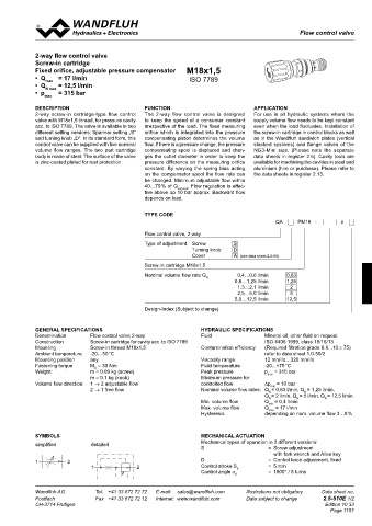
2-way flow control valve
NG3-Mini NG4-Mini NG6 ISO NG10 ISO Screw-in cartridge
Fixed orifice, adjustable pressure compensator M18x1,5
A P T B A P T B A P T B • Q = 17 l/min ISO 7789
Types A P T B A P T B • Q max = 12,5 l/min
N max
• p max = 315 bar
QD.FA10-A/B
DESCRIPTION FUNCTION APPLICATION
A P T B A P T B A P T B 2.5-762 2-way screw-in cartridge-type flow control The 2-way flow control valve is designed For use in all hydraulic systems where the
A P T B A PT B valve with M18x1,5 thread, for pressure cavity to keep the speed of a consumer constant supply volume flow needs to be kept constant
acc. to ISO 7789. The valve is available in two irrespective of the load. The fixed measuring even when the load fluctuates. Installation of
different setting versions: Spanner setting „S“ orifice which is integrated into the pressure the screw-in cartridge in control blocks as well
QD.SA06-P QD.SA10-P and turning knob „D“. In its standard form, this compensating piston determines the volume as in the Wandfluh sandwich plates (vertical
control valve can be supplied with five nominal flow. If there is a pressure change, the pressure stacked systems) and flange valves of the
A B A P T B A P T B 2.5-742 2.5-762 volume flow ranges. The two part cartridge compensating spool is displaced and chan- NG3-Mini size. (Please note the separate
A P T B A P T B body is made of steel. The surface of the valve ges the outlet diameter in order to keep the data sheets in register 2.5). Cavity tools are
is zinc-coated plated for rust protection. pressure difference on the measuring orifice available for machining the cavities in steel and
constant. By varying the spring bias acting aluminium (hire or purchase). Please refer to
UZFSA04 UZFSA06 on the compensator spool the flow rate can the data sheets in register 2.13.
A P T B A P T B 2.5-820 2.5-840 be changed. Minimum adjustable flow within
. Flow regulation is effec-
40…70 % of Q
nominal
A P T B A PT B A P T B tive above ∆p 10 bar approx. Backward flow
depends on load.
UDFSA06
2.5-840 TYPE CODE
A P T B A P T B QA PM18 - #
A P T B A PT B A P T B
Flow control valve, 2-way
VQSA04-A. VQSA06-A. VQSA10-A. Type of adjustment Screw S
Turning knob D
A P T B A P T A B P T B A P T B 2.5-920 2.5-940 2.5-960 Cover A (see data sheet 2.0-50)
A P T B A A P T P B BT APT B
Screw-in cartridge M18x1,5
Nominal volume flow rate Q 0,4…0,6 l/min 0,63
VQSA04-B. VQSA06-B. VQSA10-B. N 0,8…1,25 l/min 1,25
A P T B A P T B A P T B 2.5-920 2.5-940 2.5-960 1,3…2,1 l/min 2
2,5…5,0 l/min
5
A P T B A PT B A PT B 5,0…12,5 l/min 12,5
Design-Index (Subject to change)
VQSA04-P. VQSA06-P. VQSA10-P.
2.5-920 2.5-940 2.5-960 Ø 17
ø
A B A P T B A P T B GENERAL SPECIFICATIONS HYDRAULIC SPECIFICATIONS
26
A P T B A P T B A PT B s3 Denomination Flow control valve 2-way Fluid Mineral oil, other fluid on request
20
Construction 10 Screw-in cartridge for cavity acc. to ISO 7789 ISO 4406:1999, class 18/16/13
30
VQSA06-T. VQSA10-T. Mounting Screw-in thread M18x1,5 Contamination efficiency (Required filtration grade ß 6...10 ≥ 75)
s10 Ambient temperature -20…50 °C refer to data sheet 1.0-50/2
15
2
2
A P T B A P T B 2.5-940 2.5-960 39,5 Mounting position any 47 Viscosity range 12 mm /s…320 mm /s
M = 30 Nm
-20...+70 °C
Fluid temperature
Fastening torque
D
A P T B A PT B A P T B APT B s19 Weight: m = 0,09 kg (screw) Peak pressure p max = 315 bar
78,5
71 ø23 m = 0,1 kg (knob) Minimum pressure for
Volume flow direction: 1 → 2 adjustable flow
VQSA04-AV. VQSA06-AV. VQSA10-AV. M18x1,5 40 2 → 1 free flow controlled flow ∆p = 10 bar
min
Nominal volume flow rates: Q = 0,63 l/min, Q = 1,25 l/min,
N
N
A P T B A P T B 2.5-920 2.5-940 2.5-960 31,5 60 Min. volume flow Q = 2 l/min, Q = 5 l/min, Q = 12,5 l/min
N
N
N
Q = 0,4 l/min
A P T B A PT B A P T B 50 Max. volume flow Q min = 17 l/min
max
Hysteresis depending on nom. volume flow 3…8 %
VQSA04-BV. VQSA06-BV. VQSA10-BV.
A P T B 2.5-920 2.5-940 2.5-960
A P T B APT B SYmbOLS mECHANICAL ACTUATION
simplified detailed Mechanical types of operation in 2 different versions:
S = Screw adjustment
with fork wrench and Allen key
1 2 D = Control knob adjustment, fixed
1 2 Control stroke S = 5 mm
b
A PT B Control angle α = 1800° / 5 turns
b
Wandfluh AG Tel. +41 33 672 72 72 E-mail: sales@wandfluh.com Illustrations not obligatory Data sheet no. Wandfluh AG Tel. +41 33 672 72 72 E-mail: sales@wandfluh.com Illustrations not obligatory Data sheet no.
Postfach Fax +41 33 672 72 12 Internet: www.wandfluh.com Data subject to change 2.5-502E 2/2 Postfach Fax +41 33 672 72 12 Internet: www.wandfluh.com Data subject to change 2.5-510E 1/2
CH-3714 Frutigen Edition 21 31 CH-3714 Frutigen Edition 10 33
A PT B Page 1151
APT B