
Page 1160 - Softbound_Edition_19_en
P. 1160
Flow control valve
Flow control valves Flow control valve
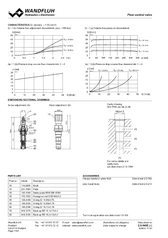
CHARACTERISTICS Oil viscosity ν = 30 mm /s 2-way flow control cartridge
2
Q = f (n) Volume flow adjustment characteristic (at p = 350 bar) Q = f (p) Volume flow pressure characteristic ◆ Q = 80 l/min M33 x 2
max
◆ Q = 70 l/min ISO 7789
Q [l/min] Q [l/min] N max
50 K0943_11 50 K0943_21 ◆ p = 350 bar
max
40 Q = 40 l/min 40 Q = 40 l/min
N
N
30 30
Q = 25 l/min Q = 25 l/min
N
N
20 20
Q N = 12 l/min
10 10 Q = 12 l/min DESCRIPTION APPLICATION
N
0 0 2-way flow control valve in screw-in cartridge construction for In all hydraulic systems in which the volume flow must be kept con-
0 0,5 1 1,5 2 2,5 n [-] 0 50 100 150 200 250 300 350 p [bar] cavity according to ISO 7789. The valve serves to maintain the stant in one flow direction when the load fluctuates. The screw-in
speed of a consumer constant independent of the load. The adjus- cartridge is perfectly suitable for installation in control blocks and
Δp = f (Q) Pressure drop volume flow characteristic 1→ 2 Δp = f (Q) Pressure drop-volume flow characteristic 1→ 3 table throttle spool determines the volume flow. When the pressure is installed in sandwich- (vertical stacked systems) and in flange
p [bar] p [bar] Q = 12 l/min Q = 25 l/min Q = 40 l/min changes, the pressure compensating piston shifts and changes the plates (corresponding data sheets in this register). For machining
30 K0943_4 25 K0943_31 N N N flow cross-section so that the pressure difference at the throttle the cartridge cavity in steel and aluminum blocks, cavity tools are
25 20 spool is kept constant. available (hire or purchase). Please refer to the data sheets in
20 15 register 2.13.
15 10
10
5 5
0 0 SYMBOL ACTUATION
0 10 20 30 40 50 Q [l/min] 0 10 20 30 40 50 Q [l/min]
Simplified Detailed Actuation Adjustment spindle M10 x 1
DImENSIONS / SECTIONAL DRAWINGS 2 2 Execution S = blockable key adjustment
Screw adjustment «S» Knob adjustment «D» Cavity drawing D = blockable knob adjustment
ISO 7789–22–04–0–98 Optionally:
Ø 17 s3 Ø26 M22x1,5 K = lockable adjustment
20 10 1 G = star handle adjustment
s 10 → see Data sheet 2.0-50
30 1 Actuation angle a = 1440 ° (4 rotations)
48,4 s 27 15 55,9 Actuation stroke S = 4 mm
b
Ø 30,4 (3) b
60
109,4 M22x1,5 116,9
61 50 (2) TYPE CODE
80
70 QZ PM33 - - #
40 (1) 2-way flow control valve
Type of adjustment Key S
(1) Control knob D
For cavity details and Cover A (see data sheet 2.0-50)
cavity tools,
see data sheet 2.13-1004 Screw-in cartridge M33 x 2
Nominal volume flow range Q 32 l/min 32
N
70 l/min 70
PARTS LIST ACCESSORIES
Flange-/sandwich plate NG6 Data sheet 2.5-742 Sealing material NBR
Position Article Description FKM (Viton) D1
Line mount body Data sheet 2.9-210
10 114.2299 Knob NBR 872 y-Z604
15 234.1060 Plate 1 3 1 3 Design index (subject to change)
20 193.1040 Safety plate RD4 DIN 6799
2 2.5-550
30 153.1302 Hexagonal nut 0,5D M6x3,2
40 160.2140 O-ring ID 14,00x1,78 2
50 160.2156 O-ring ID 15,60x1,78
60 160.2188 O-ring ID 18,77x1,78
70 049.3176 Back-up RD 14,1x17x1,4
80 049.3196 Back-up RD 16,1x19x1,4 Technical explanation see data sheet 1.0-100
Wandfluh AG Tel. +41 33 672 72 72 E-mail: sales@wandfluh.com Illustrations not obligatory Data sheet no
Postfach Fax +41 33 672 72 12 Internet: www.wandfluh.com Data subject to change 2.5-540E 2/2 www.wandfluh.com Illustrations are not binding Data subject to change 1/3 Edition: 19 25 2.5-550 E
CH-3714 Frutigen Edition 11 20
Page 1160