
Page 1162 - Softbound_Edition_19_en
P. 1162
Flow control valve
Flow control valve Flow control valve
GENERAL SPECIFICATIONS HYDRAULIC SPECIFICATIONS DIMENSIONS
Designation 2-way flow control cartridge Working pressure p = 350 bar Key adjustment „S” Control knob adjustment „D”
max
Mounting Screw-in cartridge construction Regelgenauigkeit ≤ 1 % s3 26
Nominal size M33 x 2 according to ISO 7789 Maximum volume flow Q = 80 l/min 17
max 30
Ambient temperature -25…+90 °C Minimum volume flow Q = 0,2 l/min
min
Weight 0,39 kg key adjustment Volume flow direction 1 → 2 adjustable flow 40 20
0,40 kg control knob adjustment Nominal volume flow Q = 32; 70 l/min s10
N
0,45 kg cover Fluid Mineral oil, other fluid on request
MTTFd 150 years Viscosity range 12 mm /s…320 mm /s 15
2
2
Temperature range -25…+90 °C (NBR) 52.3 s36 59.8
fluid -20…+90 °C (FKM)
Contamination Class 18 / 16 / 13 Ø40
efficiency
Filtration Required filtration grade ß 6…10 ≥ 75, 103.3 110.8
see data sheet 1.0-50
M33x2 50
PERFORMANCE SPECIFICATIONS 51 2(T)
Oil viscosity u = 30 mm /s
2
HYDRAULIC CONNECTION
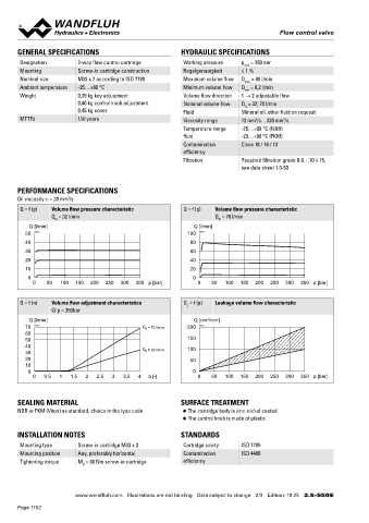
Q = f (p) Volume flow pressure characteristic Q = f (p) Volume flow pressure characteristic Cavity drawing according to ISO 7789–33–01–0–98
Q = 32 l/min Q = 70 l/min 70
N
N
Q [l/min] Q [l/min] 60 M33 x 2
50 K0821 100 K0915 1(P)
40 80
Cover „A”
30 60 23 (2)
20 40
10 20
0 0 25
0 50 100 150 200 250 300 350 p [bar] 0 50 100 150 200 250 300 350 p [bar] (1)
(1)
Q = f (n) Volume flow adjustment characteristics Q = f (p) Leakage volume flow characteristic Note! For detailed cavity drawing and cavity tools see data
L
@ p = 350bar 59 sheet 2.13-1005
Q [l/min] Q [cm /min]
3
70 K0914 Q = 70 l/min 200 K0913
N
60
50 150 110
40 Q N = 32 l/min 100 PARTS LIST
30
20 50 Position Article Description
10 15 234.1060 Washer DIN 125A M6
0 0
0 0,5 1 1,5 2 2,5 3 3,5 4 n [-] 0 50 100 150 200 250 300 350 p [bar] 20 114.2299 Control knob
25 032.0611 Cover rd 23 / 3 x 35
ACCESSORIES
30 193.1040 Retainer rd 4 DIN 6799
SEALING MATERIAL SURFACE TREATMENT Types of adjustment for screw-in Data sheet 2.0-50 40 153.1302 Hexagon nut 0,5d M6 x 3,2
NBR or FKM (Viton) as standard, choice in the type code ◆ The cartridge body is zinc-nickel coated cartridges 50 160.2298 O-ring ID 29,82 x 2,62 (NBR)
◆ The control knob is made of plastic Flange body / sandwich plate NG10 Data sheet 2.5-760 160.6296 O-ring ID 29,82 x 2,62 (FMK)
Threaded body Data sheet 2.9-205 60 160.2238 O-ring ID 23,81 x 2,62 (NBR)
INSTALLATION NOTES STANDARDS Technical explanations Data sheet 1.0-100 160.6238 O-ring ID 23,81 x 2,62 (FMK)
Mounting type Screw-in cartridge M33 x 2 Cartridge cavity ISO 7789 Filtration Data sheet 1.0-50 70 049.3297 Backup ring rd 24,5 x 29 x 1,4
Mounting position Any, preferably horizontal Contamination ISO 4406
Tightening torque M = 80 Nm screw-in cartridge efficiency
D
Wandfluh AG Postfach CH-3714 Frutigen
Tel. +41 33 672 72 72 Fax +41 33 672 72 12 sales@wandfluh.com
www.wandfluh.com Illustrations are not binding Data subject to change 2/3 Edition: 19 25 2.5-550 E www.wandfluh.com Illustrations are not binding Data subject to change 3/3 Edition: 19 25 2.5-550 E
Page 1162