
Page 1163 - Softbound_Edition_19_en
P. 1163
Flow control valve
Flow control valve
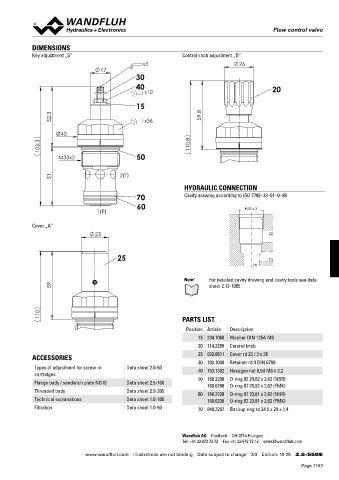
DIMENSIONS
Key adjustment „S” Control knob adjustment „D”
s3 26
17
30
40 20
s10
15
52.3 s36 59.8
Ø40
103.3 110.8
M33x2 50
51 2(T)
HYDRAULIC CONNECTION
70 Cavity drawing according to ISO 7789–33–01–0–98
60
1(P) M33 x 2
Cover „A”
23 (2)
25 (1)
(1)
Note! For detailed cavity drawing and cavity tools see data
59 sheet 2.13-1005
110 PARTS LIST
Position Article Description
15 234.1060 Washer DIN 125A M6
20 114.2299 Control knob
25 032.0611 Cover rd 23 / 3 x 35
ACCESSORIES
30 193.1040 Retainer rd 4 DIN 6799
Types of adjustment for screw-in Data sheet 2.0-50 40 153.1302 Hexagon nut 0,5d M6 x 3,2
cartridges
Flange body / sandwich plate NG10 Data sheet 2.5-760 50 160.2298 O-ring ID 29,82 x 2,62 (NBR)
160.6296 O-ring ID 29,82 x 2,62 (FMK)
Threaded body Data sheet 2.9-205 60 160.2238 O-ring ID 23,81 x 2,62 (NBR)
Technical explanations Data sheet 1.0-100 160.6238 O-ring ID 23,81 x 2,62 (FMK)
Filtration Data sheet 1.0-50 70 049.3297 Backup ring rd 24,5 x 29 x 1,4
Wandfluh AG Postfach CH-3714 Frutigen
Tel. +41 33 672 72 72 Fax +41 33 672 72 12 sales@wandfluh.com
www.wandfluh.com Illustrations are not binding Data subject to change 3/3 Edition: 19 25 2.5-550 E
Page 1163