
Page 1167 - Softbound_Edition_19_en
P. 1167
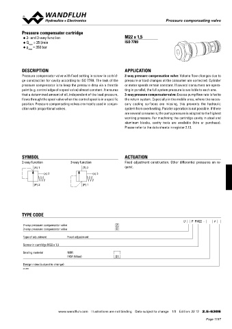
Pressure compensator valve
 Flow control valves                                                                  Pressure compensating valve


 CHARACTERISTICS Oil viscosity  ν = 30 mm 2 /s  Pressure compensator cartridge   M22 x 1,5
 Q = f (n) Volume flow adjustment characteristics (at p = 350 bar)  Q = f (p) Volume flow pressure characteristic  ◆  2- and 3-way function
             ◆  Q  = 25 l/min                                    ISO 7789
                max
 Q [l/min]  Q [l/min]  ◆  p  = 350 bar
 120  K0944_1  120  K0944_2  max
 Q  = 100 l/min
 100  N  100  Q  = 100 l/min
 N
 80  80
 60  Q N  = 50 l/min  60  Q N  = 50 l/min
 40  40     DESCRIPTION                                          APPLICATION


 20  20     Pressure compensator valve with fixed setting in screw-in cartrid-  2-way pressure compensation valve: Volume flow changes due to
 0  0
 0  1  2  3  4  n [-]  0  50  100  150  200  250  300  350 p [bar]  ge construction for cavity according to ISO 7789. The task of the   pressure or load changes at the consumer are corrected. Cylinder
            pressure compensator is to keep the pressure drop via a throttle   or motor speeds remain constant. If several consumers are opera-
 Δp = f (Q) Pressure drop volume flow characteristic  1→ 2  Δp = f (Q) Pressure drop volume flow characteristic  1→ 3  point (e.g. control edge of a spool valve) almost constant. It ensures   ting in parallel, the full system pressure is available to each one.
            that a determined amount of oil, independent of the load pressure,   3-way pressure compensator valve: Excess pump flow rate is fed to
 p [bar]  p [bar]  flows through the spool valve when the control spool is in a specific   the return system. Especially in the mobile area, where the neces-
 N
 40  K0944_3  15  K0944_4  Q  = 50 l/min
            position. Pressure compensating valves are mostly used in conjun-  sary  cooling  surfaces  are  missing,  this  prevents  the  hydraulic

 30  12  Q N  = 100 l/min  ction with proportional valves.           system from overheating. Parallel operation is not possible. If there

 9                                                               are several consumers, the pump pressure is adapted to the  highest
 20
 6                                                               working pressure. For machining the cartridge cavity in steel and
 10  3                                                           aluminum  blocks,  cavity  tools  are  available  (hire  or  purchase).
                                                                   Please refer to the data sheets in register 2.13.
 0  0
 0   20   40   60   80  100 120 130 140  Q [l/min]  0  20  40  60  80  100  120 Q [l/min]
 DImENSIONS / SECTIONAL DRAWING
 Screw adjustment «S»      Knob adjustment «D»  Cavity drawing acc. to
 ISO 7789–33–04–0–98
 Ø26        SYMBOL                                               ACTUATION
 s3
 Ø 17  M33x2  2-way function          3-way function             Fixed  adjustment  construction.  Other  differential  pressures  on  re-
 20  10           (A) 1                    (T) 2                 quest.
 s 10                   (x) 3                    (x) 3
 30
 52,3  15  59,8
 s36  (3)         (P) 2                    (P) 1
 Ø 40
 60
 133,05  M 33x2  140,55  (2)


 80,75  50  (1)
 80         TYPE CODE
                                                                                               U     F  PM22  -     #
 70  (1)     2-way-pressure compensator valve                Z
 40  For cavity details and  3-way-pressure compensator valve   D
 cavity tools, see data sheet
 2.13-1040   Type of adjustment     Fixed adjustment
 PARTS LIST  ACCESSORIES  Screw-in cartridge M22 x 1,5
 Flange-/sandwich plate NG10   Data sheet 2.5-762
 Position  Artikcle  Description  Sealing material   NBR
 10  1  114.2299  Knob  1  3  Line mount body   Data sheet 2.9-210     FKM (Viton)   D1
 3
 15  234.1060  Plate  Design index (subject to change)
 2
 20  193.1040  Safety plate RD4 DIN 6799
             2.5-630
 30  153.1302  Hexagonal nut 0,5D M6x3,2
 2
 40  160.2236  O-ring ID 23,52x1,78
 50  160.2238  O-ring ID 23,81x2,62
 60  160.2298  O-ring ID 29,82x2,62
 70  049.3276  Back-up ring RD 24,1x27x1,4
 80  049.3297  Back-up ring RD 24,5x29x1,4
 Technical explanation see data sheet 1.0-100

 Wandfluh AG   Tel.  +41 33 672 72 72   E-mail:  sales@wandfluh.com   Illustrations not obligatory   Data sheet no.
 Postfach   Fax  +41 33 672 72 12   Internet:  www.wandfluh.com   Data subject to change   2.5-555E 2/2  www.wandfluh.com  Illustrations are not binding  Data subject to change  1/3  Edition: 22 12  2.5-630 E
 CH-3714 Frutigen     Edition 10 33
                                                                                                           Page 1167