Page 1066 - Softbound_Edition_19_en
P. 1066

Proportional
                                                                          Proportional pressure reducing valve
                                                                         Proportional pressure reducing valve                                                                                                    pressure reducing valves


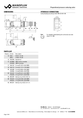
       DIMENSIONS                                          HYDRAULIC CONNECTION                                                    Proportional pressure reducing valve
                                                           Cavity drawing according to ISO 7789–33–04–0–98                         Screw-in cartridge construction                M33x2
                                                                                                                                   •  Integrated amplifier or controller electronics   ISO 7789
                                      s32                                         M33x2                                            •  Pilot operated
            15                        M33x2                                                                                        •  Q max    =  160 l/min
         78.2   MD=5.5Nm                   (3)  (2)                                                                                •  p  max    =  400 bar
          37.1                                       (1)                                (3)                                        •  p N red max  =  350 bar
           W =                                                                          (2)
                                                                                                                                   DESCRIPTION                        FUNCTION                           APPLICATION
            12   17    10    18      50   70  60  90  80
         MD=5Nm                                                                         (1)                                        Pilot operated proportional pressure reducing   The  proportional  pressure  reducing  valve   Proportional  pressure  reducing  valves  with
                          86.1              77.9                                                                                   valve with integrated electronics as screw-in   controls the pressure in port A (1). Proportio-  integrated electronics are perfectly suitable for
                                                                                   (1)
                                 170.2                                                                                             cartridge. Thread M22x1,5 for cavity according   nally to the seolenoid current, the solenoid   demanding applications in which the pressure
                                                                                                                                   ti ISO 7789. The Plug & Play valves are factory   force and the pressure in port A (1) rise. The   frequently has to be changed. They are used
                                                           Note!    For detailed cavity drawing and cavity tools see data          set and adjusted and have a high valve-to-  valve functions practically independently of the   in applications where  high valve-to-valve re-
                                              HB0                                                                                  valve reproducibility. With protection IP67 for   pressure in port P (2). The control takes place   producibility, easy installation, comfortable ope-
                                             15                     sheet 2.13-1040                                                the electronics, these valves are suitable for-  via an analog interface or a fieldbus interface   ration and high precision are very important.
                                          MD= 9.5Nm                                                                                harsh environmental conditions. As standard,   (CANopen, J1939 or Profibus DP). The pa-  The applications are in the industrial as well as
           77.3                                                                                                                    4 pressure ranges are available. The adjust-  rameterisation takes place by means of the   in the mobile hydraulics. The proportional pres-
            35                                                                                                                     ment takes place by a Wandfluh proportional   free of cost parameterisation and diagnostics   sure reducing cartridge is perfectly suitable for
             M  =                                                                                                                  solenoid (VDE standard 0580). The cartridge   software «PASO» or via Feldbus interface. The   installation in control blocks as well as in flange
                                                                                                                                                                                                         and sandwich valves of the size NG10 (please
                                                                                                                                                                      USB parameterisation interface is accessible
                                                                                                                                   body as well as the solenoid  made of steel
                                                                                                                                   are zinc coated and therefore rust protected.  through a cover flap. «PASO» is a Windows   refer to separate data sheets in register 2.3).
                       10                                                                                                          The electronics housing is made of aluminium.  programm  in  the  flow  diagram  style,  which   For machining the cartridge cavity in steel and
                                                                                                                                   Optionally these valves are available with inte-  enables the intuitive adjustment and storing   aluminum  blocks,  cavity  tools  are  available
                                                                                                                                   grated controller. As feedback value generator,   of all variable parameters. The data remain   (hire or purchase). Please refer to the data
                                                                                                                                   sensors with voltage or current output can be   saved in case of a power failure and can also   sheets in register 2.13.
       PARTS LIST                                                                                                                  directly  connected. The  available  controller   be reproduced and transferred to other DSVs.
                                                                                                                                   structures are optimised for the utilisation with
        Position Article  Description                                                                                              hydraulic drives.
            10 206.2…  W.S37 / 19 x 50
               260.5…  M.S35 / 19 x 50
            12 154.2700  Knurled nut                                                                                               TYPE CODE
            15 253.8000  HB4,5 manual override                                                                                                                                        M  V  P  PM33 -    -    /  M  E       -    HB4,5 #
               239.2033  HB0 Screw plug                                                                                            Pressure reducing valve
            17 160.2187  O-ring ID 18,72 x 2,62 (NBR)
                                                                                                                                   Pilot operated
            18 160.2170  O-ring ID 17,17 x 1,78 (NBR)                                                                              Proportional
            50 160.2298  O-ring ID 29,82 x 2,62 (NBR)
               160.6296  O-ring ID 29,82 x 2,62 (FMK)                                                                              Screw-in thread M33x2
                                                                                                                                   Nominal pressure range p                    100 bar   100
            60 160.2235  O-ring ID 23,47 x 2,62 (NBR)                                                                                                 N red                    200 bar   200
               160.6235  O-ring ID 23,47 x 2,62 (FKM)                                                                                                                         275 bar   275
            70 049.3297  Backup ring rd 24,5 x 29 x 1,4                                                                                                                       350 bar   350
            80 160.2219  O-ring ID 21,89 x 2,62 (NBR)                                                                              Nominal voltage U       12 VDC                     G12
                                                                                                                                                N
               160.6216  O-ring ID 21,89 x 2,62 (FKM)                                                                                                      24 VDC                     G24
            90 049.3277  Backup ring rd 22,5 x 27 x 1,4                                                                            Slip-on coil            Metal housing, square
                                                                                                                                   Connection execution    Integrated electronics
                                                                                                                                   Hardware configuration
                                                                                                                                   With analog command value signal (0…+10 V preset)   A1
                                                                                                                                   With CANopen according to DSP-408                   C1
                                                                                                                                   With Profibus DP in accordance with Fluid Power Technology   P1
                                                                                                                                   With CAN J1939 (on request)                          J1
                                                                                                                                   Function
                                                                                                                                   Amplifier
                                                                                                                                   Controller with current feedback value signal (0...20 mA / 4...20 mA)   R1
                                                                                                                                   Controller with voltage feedback value signal (0...10 V)   R2
                                                                                                                                   Dichtwerkstoff          NBR
                                                                                                                                                           FKM (Vitron)                D1
                                                                                                                                   Manual override
                                                                                                                                   Design-Index (Subject to change)
                                                           Wandfluh AG  Postfach  CH-3714 Frutigen
                                                           Tel. +41 33 672 72 72  Fax +41 33 672 72 12  sales@wandfluh.com
                                                                                                                                   Wandfluh AG         Tel.  +41 33 672 72 72   E-mail:  sales@wandfluh.com   Illustrations not obligatory   Data sheet no.
                         www.wandfluh.com  Illustrations are not binding  Data subject to change  4/4  Edition: 17 48  2.3-649 E   Postfach            Fax  +41 33 672 72 12   Internet:  www.wandfluh.com   Data subject to change   2.3-652E 1/4
                                                                                                                                   CH-3714 Frutigen                                                                             Edition 17 01
       Page 1066
   1061   1062   1063   1064   1065   1066   1067   1068   1069   1070   1071