
Page 994 - Softbound_Edition_19_en
P. 994
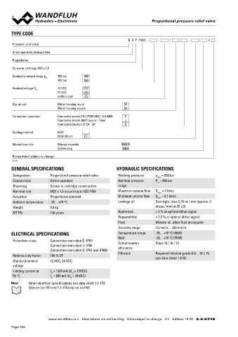
Proportional pressure relief valve
Proportional pressure relief valve Proportional pressure relief valve
TYPE CODE PERFORMANCE SPECIFICATIONS
2
B S P PM22 - - / - # Oil viscosity u = 30 mm /s
Pressure relief valve p = f (Q) Pressure volume flow characteristics p = f (Q) Pressure volume flow characteristics
red
red
Direct operated, leakage-free Maximal adjustable pressure Minimal adjustable pressure
p [bar] p [bar]
Proportional 500 K1168 p = 450 bar 6 K1169
N
Screw-in cartridge M22 x 1,5 400 p N = 350 bar 5
300 4
Nominal pressure range p 350 bar 350 200 3
N
450 bar 450 2
100 1
Nominal voltage U 12 VDC G12
N 0 0
24 VDC G24 0 0,4 0,8 1,2 1,6 2,0 Q [l/min] 0 0,4 0,8 1,2 1,6 2,0 Q [l/min]
without coil X5
Slip-on coil Metal housing round W
Metal housing square M p = f (n) Pressure adjustment characteristics
red
Measured at Q = 1 l/min
Connection execution Connector socket EN 175301-803 / ISO 4400 D
Connector socket AMP Junior - Timer J p [bar]
Connector Deutsch DT04 - 2P G 500 K1170
400
Sealing material NBR
FKM (Viton) D1 300
200
Manual override Manual override HB4,5
Screw plug HB0 100
0
Design index (subject to change) 0 10 20 30 40 50 60 70 80 90 100 l [%]
2.3-571
GENERAL SPECIFICATIONS HYDRAULIC SPECIFICATIONS
Designation Proportional pressure relief valve Working pressure p = 500 bar ACCESSORIES SEALING MATERIAL
max NBR or FKM (Viton) as standard, choice in the type code
Construction Direct operated Nominal pressure P = 450 bar Proportional amplifier Register 1.13
N
Mounting Screw-in cartridge construction range Electric plug B (black) Article no. 219.2002
Nominal size M22 x 1,5 according to ISO 7789 Maximum volume flow Q = 2 l/min Flange body / sandwich plate NG4-Mini Data sheet 2.3-720
max
Actuation Proportional solenoid Minimum volume flow Q = 0,1 l/min Flange body / sandwich plate NG6 Data sheet 2.3-740
min
Ambient temperature -25…+70 °C Leakage oil Seat tight, max. 0,15 ml / min (approx. 3 Flange body / sandwich plate NG10 Data sheet 2.3-760 SURFACE TREATMENT
Weight 0,6 kg drops / min) at 30 cSt Threaded body Data sheet 2.9-200 ◆ The cartridge body made of steel and the slip-on coil are
MTTFd 150 years Hysteresis ≤ 3 % at optimal dither signal Technical explanations Data sheet 1.0-100 zinc-nickel coated
Repeatability ≤ 1,5 % at optimal dither signal
Fluid Mineral oil, other fluid on request Filtration Data sheet 1.0-50
2
Viscosity range 12 mm /s…320 mm /s
2
ELECTRICAL SPECIFICATIONS Temperature range -25…+70 °C (NBR)
fluid -20…+70 °C (FKM)
Protection class Connection execution D: IP65 Contamination Class 18 / 16 / 13
Connection execution J: IP66 efficiency
Connection execution G: IP67 and IP69K STANDARDS INSTALLATION NOTES
Relative duty factor 100 % DF Filtration Required filtration grade ß 6…10 ≥ 75, Cartridge cavity ISO 7789 Mounting type Screw-in cartridge M22 x 1,5
see data sheet 1.0-50
Standard nominal 12 VDC, 24 VDC Solenoids DIN VDE 0580 Mounting position Any, preferably horizontal
voltage Connection execution D EN 175301 – 803 Tightening torque M = 60 Nm Screw-in cartridge
D
Limiting current at I = 1320 mA (U = 12VDC) Protection class EN 60 529 M = 5 Nm knurled nut
N
G
50 °C I = 660 mA (U = 24VDC) D
G N Contamination efficiency ISO 4406 M = 9,5 Nm HB0
D
Note! Other electrical specifications see data sheet 1.1-173 M = 5,5 Nm HB4,5
D
(slip-on coil W) and 1.1-174 (slip-on coil M)
www.wandfluh.com Illustrations are not binding Data subject to change 2/4 Edition: 19 29 2.3-571 E www.wandfluh.com Illustrations are not binding Data subject to change 3/4 Edition: 19 29 2.3-571 E
Page 994