
Page 993 - Softbound_Edition_19_en
P. 993
Proportional
Proportional pressure relief valve
pressure relief valves Proportional pressure relief valve
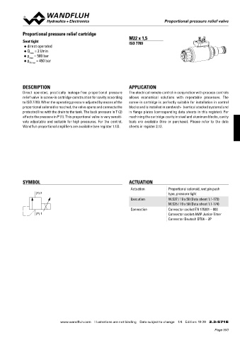
Proportional pressure relief cartridge
DIMENSIONS / SECTIONAL DRAWINGS
*Adjusting screw for setting the nominal pressure (-20 % / +30 %) Seat tight M22 x 1,5
With analog interface E: Venting direct operated ISO 7789
Amplifier and Controller 25,30 21, 22 40 - Release locknut ◆ Q = 2 l/min
- Remove screw ◆ max
- Press check-valve (with a pin or with allen key < 1,3 mm) ◆ p = 500 bar
max
X2 - Screw the screw back in ◆ p = 450 bar
25,30 21, 22 40 X1 - Set the required pressure and tighten the lock nut N max
X2
83 X4 (nur Regler)
X1 s6 (controller only) M22x1.5
s30 70 60
DESCRIPTION APPLICATION
83 X4 (nur Regler)
s6 (controller only) M22x1.5 Direct operated, practically leakage-free proportional pressure The electrical remote control in conjunction with process controls
s30 70 60 35 P(1) relief valve in screw-in cartridge construction for cavity according allows economical solutions with repeatable processes. The
17.5 E T(2) to ISO 7789. When the operating pressure adjusted by means of the screw-in cartridge is perfectly suitable for installation in control
35 17 P(1) 95 18 proportional solenoid is reached, the valve opens and connects the blocks and is installed in sandwich- (vertical stacked systems) and
13 20 50 Under pressure oil shoot out!
17.5 E T(2) 135.4 37 Cover with a cloth. protected line with the drain to the tank. The back pressure in T (2) in flange plates (corresponding data sheets in this register). For
17 M D = 10 Nm 18 172.4 affects the pressure in P (1). This proportional valve is very sensiti- machining the cartridge cavity in steel and aluminum blocks, cavity
13 20 95 50 vely adjustable and suitable for high pressures. For the control, tools are available (hire or purchase). Please refer to the data
135.4 37
M D = 10 Nm With fieldbus interface With fieldbus interface Wandfluh proportional amplifiers are available (see register 1.13). sheets in register 2.13.
172.4
Amplifier Controller
X2
X1
X2 X2
X1
X1
X2 X3
P (1)
X1 X3 101
P (1) 83 X3 X4
101
83 T (2) X3 s30 X4 M22x1.5 s30 M22x1.5
T (2) s30 M22x1.5 s30 M22x1.5
35 P(1) 35 P(1)
35 17.5 P(1) 35 17.5 P(1) SYMBOL ACTUATION
17.5 T(2) 17.5 T(2) T(2) 90.2 37 T(2) Actuation Proportional solenoid, wet pin push
90.2 37 90.2 37 (T) 2 type, pressure tight
90.2 37 127.2 M22x1,5 127.2
127.2 127.2 Execution W.S37 / 19 x 50 (Data sheet 1.1-173)
Cavity drawing according to M.S35 / 19 x 50 (Data sheet 1.1-174)
ISO 7789–22–02–0–98 Connection Connector socket EN 175301 – 803
(P) 1 Connector socket AMP Junior-Timer
For detailed cavity drawing (2)
PARTS LIST and cavity tools Connector Deutsch DT04 – 2P
Position Article Description see data sheet 2.13-1003
(1)
17 160.2187 O-ring ID 18,72 x 2,62 (NBR)
18 160.2170 O-ring ID 17,17 x 1,78 (NBR) (1)
20 154.2700 Knurled nut ACCESSORIES
21 223.1317 Dummy plug M16 x1,5 • Cartridge built in: see register 2.3
flange and sandwich bodies
22 160.6131 O-ring ID 13,00 x1,5 • Set-up software see start-up
25 062.0102 Cover square • Cable to adjust the settings through interface USB
30 072.0021 Gasket 33,2 x 59,9 x 2 (from plug type A to Mini B, 3 m) article no. 219.2896
40 208.0100 Socket head cap screw M4 x10 • Cable connector for analog interface:
50 160.2188 O-ring ID 18,77 x 1,78 (NBR) – straight, soldering contact article no. 219.2330
160.6188 O-ring ID 18,77 x 1,78 (FKM) – 90°, soldering contact article no. 219.2331
60 160.2140 O-ring ID 14,00 x 1,78 (NBR) Recommended cable size:
– Outer diameter 9…10,5 mm
160.6141 O-ring ID 14,00 x 1,78 (FKM) – Single wire max. 1 mm 2
70 049.3177 Back-up ring RD 14,6 x 17,5 x 1,4 – Recommended wire size:
0…25 m = 0,75 mm (AWG18)
2
25…50 m = 1 mm (AWG17)
2
Technical explanation see data sheet 1.0-100
Wandfluh AG Tel. +41 33 672 72 72 E-mail: sales@wandfluh.com Illustrations not obligatory Data sheet no.
Postfach Fax +41 33 672 72 12 Internet: www.wandfluh.com Data subject to change 2.3-562E 4/4 www.wandfluh.com Illustrations are not binding Data subject to change 1/4 Edition: 19 29 2.3-571 E
CH-3714 Frutigen Edition 17 01
Page 993