
Page 989 - Softbound_Edition_19_en
P. 989
25,30
X2
X1 21, 22 40 X1 X2
83 X4 (Nur Regler) 18 50 70 60 83 X3 Proportional Proportional
pressure relief valves
(controller only) pressure relief valves Proportional pressure relief valve
15
DIMENSIONS / SECTIONAL DRAWINGS
With analog interface Proportional pressure relief valve inverse
P(1)
35 Amplifier and Controller 25,30 21, 22 40 Cavity drawing according to P(1) Screw-in cartridge M22x1,5
35
17.5 T(2) 17.5 ISO 7789–22–02–0–98 • Integrated amplifier or controller electronics ISO 7789
• Direct operated
s30 M 22x1.5 T(2) • Q = 20 and 25 l/min
17 X2 M22x1,5 s 30 M 22x1.5 max X2
20 135 95 90 (37) • p max = 400 bar
X1
(37) X1 127 • p N max = 350 bar
172
83 X4 (Nur Regler) 18 50 70 60 (2) 83 DESCRIPTION FUNCTION APPLICATION
X3
Direct operated proportional pressure relief
The valve limits the pressure in the port P
Proportional pressure relief valves with
(controller only)
15 valve with integrated electronics and inverse (1) and reliefs the volume flow to tank port inte-grated electronics are well suited for
function. Thread M22x1,5 for cavity according T (2). The back pressure in T (2) influences demanding applications, in which the pres-
(1) to ISO 7789. These plug & play valves are the pressure in P (1). The reliefed pressure sure frequently has to be changed. They
factory set and adjusted. High valve-to-valve drops with rising solenoid current (inverse are implemented in systems calling for good
T(2) 35 P(1) (1) reproducibility. Housing for electronics with function), and the with deenergised solenoid, valve-to-valve reproducibility, easy installati-
P(1)
35
17.5 T(2) For detailed cavity drawing 17.5 protection class IP67 for harsh environment. a maximum pressure is present. The control on, comfortable operation and high precision
connection is provided by an analog interface
As standard versions, 6 pressure ranges are
in industrial hydraulics as well as in mobile
M 22x1.5
or a fieldbus interface (CANopen or Profibus
available: 20, 40, 63, 100, 160, 200, 315 and
T(2)
hydraulics. The proportional pressure relief
s 30
see data sheet 2.13-1003
17 s30 M 22x1.5 and cavity tools 350 bar. Good flow performance due to the DP). Parameter setting and diagnosis with catridge is very suitable for mounting in control
the free-of-charge software «PASO» or via
differential area principle. Small leakage along
blocks, flange bodies and sandwich plates size
90
(37)
20 135 95 the poppet guide. Adjustment by a Wandfluh fieldbus interface. After taking off the cover of NG4-Mini and NG6. (Please note the separate
127
P(1) (37) (VDE-Norm 0580) proportional solenoid. The the electronic housing, the serial interface to data sheets in register 2.3). Cavity tools are
172 cartridge and the solenoid made of steel are adjust the settings is accessible. The menu available for machining the cavities in steel and
25,30 21, 22 40 zinc coated and therefore rust-protected. controlled Windows program «PASO» allows aluminium (hire or purchase). Please refer to
With fieldbus interface With fieldbus interface easy adjustment of all variable settings. Data the data sheets in register 2.13.
Amplifier Controller are stored in a non-volatile memory. Even after
an electric power failure settings can easily be
X2 reproduced and transmitted.
X2 X2
X1 X1 X1 T(2)
83 X4 (Nur Regler) 18 50 70 60 83 X3 X3 TYPE CODE
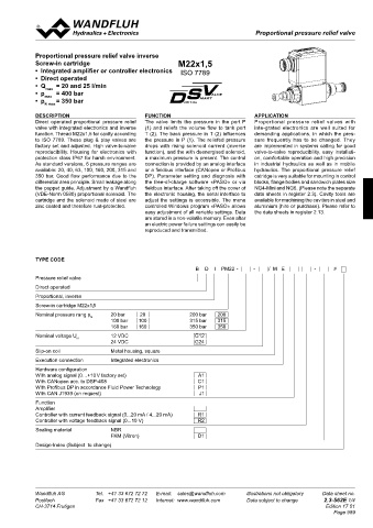
(controller only) B D I PM22 - - / M E - #
15 101
X4 Pressure relief valve
P(1) Direct operated
35 P(1) 35 P(1) Proportional, inverse
17.5 T(2) 17.5 Screw-in cartridge M22x1,5
s30 M 22x1.5 s 30 M 22x1.5 T(2) Nominal pressure rang p 20 bar 20 200 bar 200
N
17 17.5 X2 100 bar 100 315 bar 315
20 135 95 (37) 90 127 (37) Nominal voltage U 160 bar 160 350 bar 350
X1
12 VDC
G12
172 PARTS LIST ACCESSOIRES N 24 VDC G24
Flange-/sandwich plate NG4-Mini Data sheet 2.3-720
Position Article Description Flange-/sandwich plate NG6 Data sheet 2.3-740 Slip-on coil Metal housing, square
X3
15 253.8000 HB 4,5 Manual override (data sheet 1.1-300) Flange-/sandwich plate NG10 Data sheet 2.3-760 101 Execution connection Integrated electronics
Line mount body
Data sheet 2.9-200
17 160.2187 O-ring ID 18,72 x 2,62 (NBR) • Set-up software see start-up Hardware configuration
X4
18 160.2170 O-ring ID 17,17 x 1,78 (NBR) • Cable to adjust the settings through interface USB With analog signal (0…+10 V factory set) A1
C1
With CANopen acc. to DSP-408
T(2) 20 154.2700 Knurled nut (from plug type A to Mini B, 3 m) article no. 219.2896 With Profibus DP in accordance Fluid Power Technology P1
21 223.1317 Dummy plug M16 x1,5 • Mating connector (plug female) for the analogue interface: With CAN J1939 (on request) J1
22 160.6131 O-Ring ID 13,00 x1,5 – straight, soldering contact article no. 219.2330 Function
25 062.0102 Cover square – 90°, soldering contact article no. 219.2331 17.5 Amplifier
Recommended cable size:
30 072.0021 Gasket 33,2 x 59,9 x 2 – Outer diameter 9…10,5 mm Controller with current feedback signal (0...20 mA / 4...20 mA) R1
Controller with voltage feedback signal (0...10 V)
R2
P(1) 40 208.0100 Socket head cap screw M4 x10 – Single wire max. 1 mm 2 Sealing material NBR
50 160.2188 O-ring ID 18,77 x 1,78 (NBR) – Recommended wire size: FKM (Vitron) D1
2
160.6188 O-ring ID 18,77 x 1,78 (FKM) 0…25 m = 0,75 mm (AWG18)
2
60 160.2140 O-ring ID 14,00 x 1,78 (NBR) 25…50 m = 1 mm (AWG17) Design-Index (Subject to change)
160.6141 O-ring ID 14,00 x 1,78 (FKM)
70 049.3177 Back-up ring RD 14,6 x 17,5 x 1,4
X2
X1 Technical explanation see data sheet 1.0-100
Wandfluh AG Tel. +41 33 672 72 72 E-mail: sales@wandfluh.com Illustrations not obligatory Data sheet no. Wandfluh AG Tel. +41 33 672 72 72 E-mail: sales@wandfluh.com Illustrations not obligatory Data sheet no.
X3
Postfach Fax +41 33 672 72 12 Internet: www.wandfluh.com Data subject to change 2.3-561E 4/4 Postfach Fax +41 33 672 72 12 Internet: www.wandfluh.com Data subject to change 2.3-562E 1/4
CH-3714 Frutigen 101 Edition 17 01 CH-3714 Frutigen Edition 17 01
X4 Page 989
17.5