Page 842 - Softbound_Edition_19_en
P. 842

Pressure sequence valve
                                                                                    Pressure sequence valves                                                                                                    Accumulator loading valve

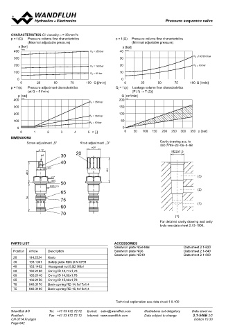
       chaRacteRistics Oil viscosity υ = 30 mm /s                                                                                  Accumulator loading cartridge
                                       2
       p = f (Q)    Pressure volume flow characteristics    p = f (Q)   Pressure volume flow characteristics                        ◆  pilopt operated                                  M22 x 1,5
               (Maximal adjustable pressure)                        (Minimal adjustable pressure)                                   ◆  p  = 400 bar                                     ISO 7789
          p [bar]                                              p [bar]                                                              ◆  p max   = 350 bar
        400  K0102                             P N  = 350 bar  40  K0112                                                               N max
                                                                                                                                    ◆  Q  = 30 l/min
                                                                                                                                       max
                                                                                                   P N   = 160/350 bar
        300                                                   30
        200                                    P N  = 160 bar  20                                  P N   = 63 bar
                                                                                                                                   DESCRIPTION                                          APPLICATION
        100                                    P N  = 63 bar  10                                                                   Pilot operated accumulator unloading valve in screw-in cartridge   Accumulator unloading valves are used in hydraulic systems with
          0                                                    0                                                                   construction for cavity according to ISO 7789. The valve has an ad-  pressure  accumulators.  They  allow  an  energy  and  cost-saving
           0        25      50       75      100  Q [l/min]     0       25       50      75      100  Q [l/min]                    justable upper switching point and a switching pressure difference   system design in the case of strongly varying oil requirement of
       p = f (n)   Pressure adjustment characteristics      Q = f (p)   Leakage volume flow characteristics                        which is fixed by the design. If the pressure in P exceeds the upper,   cylinders, or for maintaining pressures over a period of time, e.g. in
                                                             L
                  (at Q = 5 l/min)                                  [P (1) → T (2)]                                                adjustable switching pressure, the pilot control is opened by the   the case of clamping procedures. The screw-in cartridge is per-
          p [bar]                                              Q [cm /min]                                                         pilot control spool.  A pilot oil flow passes, and the reverse side of   fectly suitable for installation in control blocks and is installed in
                                                                   3
        400  K0113                                           200  K0114
                                              P N  = 350 bar                                                                       the  main  spool  is  unloaded.  The  produced  pressure  difference   sandwich-  (vertical stacked systems) and in flange plates (corres-
        300                                                  150                                                                   shifts the main spool against the spring, and the valve switches to   ponding data sheets in this register). For machining the cartridge
        200         P(1)                                     100                                                                   unloading circuit. Due to the surface difference in the pilot control   cavity in steel and aluminum blocks, cavity tools are available (hire

                                              P N  = 160 bar                                                                       part, the pilot oil flow is interrupted, as soon as the pressure in the   or purchase). Please refer to the data sheets in register 2.13.

        100                                                   50                                                                   accumulator drops by 15 %, resp. 25 % of the upper switching point.
                                              P N  = 63 bar                                                                                                                             Note!    An additional pressure relief valve must be present for
          0                                                    0                                                                   Pressures at the main spool balance out, and the spring shifts the   the system protection. Please observe the adjustment
                         2
           0    x(3) 1  A(2)    3      4      5  n [-]          0    50   100 150   200   250  300   350  p [bar]                  main spool into the closed position. The pump can now again build   and connection example in the „Symbol” section.
                                                                                                                                   up the system presssure up to the upper switching point, the cycle
       DiMensions                                                                                                                  starts again.

               Screw adjustment „S“       Knob adjustment  „D“                    Cavity drawing acc. to
                                                                                  ISO 7789–22–06–0–98
                                               ø 26
                     Ø  17                                                              M22x1,5
                      s4        30      20                                                                                         SYMBOL
                                40                                                                                                                                                      Adjustment and connection example
                                                                                                                                          (T) 2                                         Upper switching point (OS) adjusted = 100 bar
                         s13                                                                                                                                                            Switching pressure difference  15 % fixed
               40,6                                     48,1                                                                         (x) 3                                              Lower switching point (US) = OS - 15 % = 85 bar
                           s27                                                                       (3)                                                                                Gas preload for accumulator max. 90 % of US = 76 bar
                           ø30
                                50
                          M22x1,5                                                                                                              (P) 1
                                65                                                                   (2)                                                                                                     3
               54               75
                                                                                                     (1)                                                                                             1           2
                                60
                                70
                                                                                          (1)
                                                                                  For detailed cavity drawing and avity
                                                                                  tools see data sheet 2.13-1006.
                                                                                                                                   TYPE CODE
                                                                                                                                                                                                                 US     PM22  -     -     #
       PaRts list                                          accessoRies                                                              Pilot operated, accumulator loading valve
                                                           Sandwich plate NG4-Mini            Data sheet 2.1-820
        Position   Article   Description                   Sandwich plate NG6                 Data sheet 2.1-840                    Type of adjustment     Key             S
                                                           Sandwich plate NG10                Data sheet 2.1-860                                           Control knob    D
        20      114.2224   Knob                                                                                                                            Cover           A   (see Data sheet 2.0-50)
        30      193.1061   Safety plate RD6 DIN 6799
        40      153.1402   Hexagonal nut 0,5D M8x1                                                                                  Screw-in cartridge M22 x 1,5
        50      160.2188   O-ring ID 18,77x1,78
        60      160.2140   O-ring ID 14,00x1,78                                                                                     Nominal pressure range p N   100 bar   100
        65      160.2156   O-ring ID 15,60x1,78                                                                                                            160 bar         160
                                                                                                                                                           350 bar
                                                                                                                                                                           350
        70      049.3176   Back-up ring RD 14,1x17x1,4
        75      049.3196   Back-up ring RD 16,1x19x1,4                                                                              Sealing material       NBR
                                                                                                                                                           FKM (Viton)     D1
                                                            Technical explanation see data sheet 1.0-100                            Design index (subject to change)
                                                                                                                                    2.1-548
       Wandfluh AG        Tel.  +41 33 672 72 72   E-mail:  sales@wandfluh.com   Illustrations not obligatory   Data sheet no.
       Postfach           Fax  +41 33 672 72 12   Internet:  www.wandfluh.com   Data subject to change   2.1-546E 2/2                                 www.wandfluh.com  Illustrations are not binding  Data subject to change  1/3  Edition: 19 24  2.1-548 E
       CH-3714 Frutigen                                                                            Edition 10 33
       Page 842
   837   838   839   840   841   842   843   844   845   846   847