
Page 839 - Softbound_Edition_19_en
P. 839
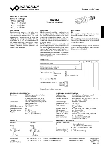
Pressure relief valve
 Pressure relief valves                                                                       Pressure relief valves

 chaRacteRistics Oil viscosity υ = 30 mm /s
 2
 p = f (Q)    Pressure volume flow characteristics   p = f (Q)   Pressure volume flow characteristics  Pressure relief valve
    (Maximal adjustable pressure)      (Minimal adjustable pressure)  screw-in cartridge  M22x1,5
 p [bar]  p [bar]  •  Direct operated
 70  K0106  20  K0104  •  Q     =   25 l/min          Wandfluh standard
 60         •  p  max    = 400 bar
 50  15     •  p max    = 350 bar
 40  10        n max
 30         DescRiPtion                        Function                           aPPlication
 20  5      Direct  operated pressure relief valve as  a   BX: If pressure in pilot line x reaches the set   BX:
 10         screw-in  cartridge with a thread M22x1,5 and   pressure poppet spool will be pushed against   Used to pilot e.g.a logic elements wich must
 0  0  0  20  40  60  80  100  Q [l/min]  cavity according to Wandfluh-Norm. The valve   the spring. Oil passage form P to T line will be   relief independent of system pressure.
 0  20  40  60  80  100  Q [l/min]  is available in 2 different setting versions: Key   opened-up irrespective of pressure in P line,   BY:
            setting „S“ and turning knob setting „D“. Key   this due to a drain connection separating x   Used to pilot e.g.a logic element with loading/
 p = f (n)   Pressure adjustment characteristics  Q = f (p)   Leakage volume flow characteristics  adjustment „S“ is also available with cover   and P line. Poppet spool and pilot piston are   unloading and relief function in an accumulator
 L
            (at Q = 5 l/min)     [P (1) → T (2)]  see data sheet 2.0-50.2 standard pressure   physically linked.  or dual pump system.
 p [bar]  Q [cm /min]  levels are available: 100 bar and 315 bar. The   BY: If pressure in pilot line x reaches the set
 3
 40  K0103  20  K0105  cartridge body made of steel is galvanized and   pressure poppet spool will be pushed against   For machining the cavity in steel or aluminium
            therefore rust-protected.          the spring. Oil passage from P to T line will be   tools are available for rent or sale. See also
 30  15                                        opened-up. Poppet spool and pilot piston are   data sheet in register 2.13
 P(1)                                          separate items. Due to the area ratio of the
 20  10                                        pilot the required pilot pressure in x line is lower
                                               than pressure in P line by the percentage of the
 10  5                                         differential pressure.
 0  0
 T(2)  0  1  2  3  4  5  6  7  n [-]  0  5  10  15  20  25  30  35  p [bar]  tYPe coDe
                                                                                                                        B       PM22  -             #
                                               Pressure relief valve
 DiMensions
 Screw adjustment «S»   Knob adjustment  «D»   Relief valve remote controlled          X
                                               Relief and unloading valve              Y
                                               Type of adjustment  Key      S
 Cavity drawing to
 Ø 26  ISO 7789–22–02–0–98                                    Control knob   D
 Ø 17                                                         Cover         A   (see data sheet 2.0-50)
 20
 s4  M22x1,5
 30                                            Screw cartridge M22x1,5
 40                                            Nominal pressure range p    100 bar  100
 s13                                                              N  315 bar  315
 57  (2)                                                             350 bar  350
 49,5
 s27                                           Design-Index (Subject to change)
 ø30  95,4  (1)
 50         GeneRal chaRacteRistics                              hYDRaulic chaRacteRistics
 M22x1,5    Description      BX: Direct operated relief valve,   Hydraulic fluid   Mineral oils, other fluids on request
 (1)                         remote controlled                   Max permissible   ISO 4406:1999, class 18/16/13
 38,4  Detailed cavity drawing and cavity        BY: Direct operated relief valve,  contamination level   (recommended filter gauge ß 10…25≥75)

                             with additional unloading function
                                                                                    see data sheet 1.0-50/2
 60  tools see data sheet 2.13-1003.  Construction   Screw-in cartridge for cavity acc. to  Viscosity range   12 mm /s…320 mm /s
                                                                                                  2
                                                                                        2
                             Wandfluh-standard                   Hydraulic fluid temp.   -20…+70°C
 70         Mounting         M22x1.5 screw thread                Peak pressure      p max  = 400 bar
            Ambient temperature   -20…+50°C                                         p Tmax = p +20 bar
                                                                                         P
            Installation position    any                         Nominal pressure   p = 100 bar, p = 315 bar, p = 350 bar
                                                                                                       N
                                                                                              N
                                                                                    N
            Tightening torque   M  = 50 Nm                       Min. pressure      see characteristic
                               D
 PaRts list  accessoRies  Weight:   m = 0,20 kg (key)            Differential pressure   11% for p = 100 bar
                                                                                          N
 Pressure relief valve:      m = 0,21 kg (control knob)          (only for BY.PM22)   7,5% for p = 315 bar and p = 350 bar
                                                                                           N
 Position   Article   Discription  Flange-/sandwich plate NG4-Mini   Data sheet 2.1-620  Volume flow   Q = 0,1…25 l/min  N
 Flange-/sandwich plate NG6   Data sheet 2.1-640                 Leak volume flow   see characteristic (BX.PM22)
 20   114.2224   Knob  Flange-/sandwich plate NG10   Data sheet 2.1-660             tight seating (BY.PM22)
 30   193.1061   Safety plate RD6 DIN 6799  Back pressure valve:  sYMBols  Mechanical actuation
 40   153.1402   Hexagonal nut 0,5D M8 x 1  Sandwich plate NG4-Mini   Data sheet 2.1-720  BX.PM22  BY.PM22  2 types of adjustments:
 50   160.2188   O-ring ID 18,77 x 1,78  Sandwich plate NG6   Data sheet 2.1-740  S   =  Screw adjustment
 Data sheet 2.1-760
 Sandwich plate NG10
 60   160.2140   O-ring ID 14,00 x 1,78  P(2)  P(2)                                 with fork wrench and Allen key
 70   049.3177   Back-up ring RD 14,6 x 17,5 x 1,4  Line mount body   Data sheet 2.9-200  D   =  Control knob adjustment, fixed
                                                                 Actuation stroke S
                                                                                  =  5 mm
                     x(1)                   x(1)                 Actuation angle α   b  =  1800° (5 revolutions)
 Technical explanation see data sheet 1.0-100                                 b
                   T(3)                  T(3)
 Wandfluh AG   Tel.  +41 33 672 72 72   E-mail:  sales@wandfluh.com   Illustrations not obligatory   Data sheet no.  Wandfluh AG   Tel.  +41 33 672 72 72   E-mail:  sales@wandfluh.com   Illustrations not obligatory   Data sheet no.
 Postfach   Fax  +41 33 672 72 12   Internet:  www.wandfluh.com   Data subject to change   2.1-542E 2/2   Postfach   Fax  +41 33 672 72 12   Internet:  www.wandfluh.com   Data subject to change   2.1-544E 1/2
 CH-3714 Frutigen                   Edition 11 18  CH-3714 Frutigen  17        ø 26                      Edition 14 22
                    Ø
                                                                                                            Page 839
                     s4         30     20
                                40
                         s13
               47,1                                      54,6
                           s27
                           ø30
                               50
                          M22x1,5
               53,5            70
                               60
                               75
                               65