Page 837 - Softbound_Edition_19_en
P. 837

Pressure relief valve
                                                                                              Pressure relief valves

            Pressure relief valve
            screw-in cartridge
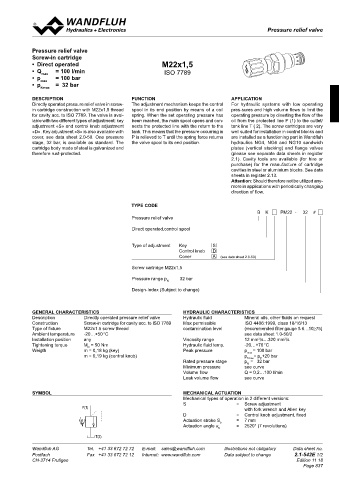
            •  Direct operated                            M22x1,5
            •  Q max    = 100 l/min                        ISO 7789
            •  p max    = 100 bar
            •  p    =  32 bar
               nmax
            DescRiPtion                        Function                           aPPlication
            Directly operated pressure relief valve in screw-  The adjustment mechanism keeps the control   For hydraulic systems with low operating
            in cartridge construction with M22x1,5 thread   spool in its end position by means of a coil   pres-sures and high volume flows to limit the
            for cavity acc. to ISO 7789. The valve is avai-  spring. When the set operating pressure has   operating pressure by diverting the flow of the
            lable with two different types of adjustment: key   been reached, the main spool opens and con-  oil from the protected line P (1) to the outlet/
            adjustment «S» and control knob adjustment   nects the protected line with the return to the   tank line T ( 2). The screw cartridges are very
            «D». Key adjustment «S» is also available with   tank. This means that the pressure occurring in   well suited for installation in control blocks and
            cover, see data sheet 2.0-50. One pressure   P is relieved to T until the spring force returns   are installed as a functioning part in Wandfluh
            stage, 32 bar, is available as standard. The   the valve spool to its end position.  hydraulics  NG4,  NG6  and  NG10  sandwich
            cartridge body made of steel is galvanized and                        plates  (vertical  stacking)  and  flange  valves
            therefore rust-protected.                                             (please see separate data sheets in register
                                                                                  2.1).  Cavity  tools  are  available  (for  hire  or
                                                                                  purchase) for the manufacture of cartridge
                                                                                  cavities in steel or aluminium blocks. See data
                                                                                  sheets in register 2.13.
                                                                                  Attention: Should therefore not be utilized any-
                                                                                  more in applications with periodically changing
                                                                                  direction of flow.

                                               tYPe coDe
                                                                                             B    K       PM22  -     32    #
                                               Pressure relief valve

                                               Direct operated,control spool

                                               Type of adjustment   Key     S
                                                                Control knob   D
                                                                Cover       A    (see data sheet 2.0-50)
                                               Screw cartridge M22x1,5
                                               Pressure range p    32 bar
                                                            N
                                               Design-Index (Subject to change)


            GeneRal chaRacteRistics                              hYDRaulic chaRacteRistics
            Description       Directly operated pressure relief valve  Hydraulic fluid   Mineral oils, other fluids on request
            Construction      Screw-in cartridge for cavity acc. to ISO 7789  Max permissible   ISO 4406:1999, class 18/16/13
            Type of fixture   M22x1.5 screw thread               contamination level   (recommended filter gauge ß 6…10≥75)
            Ambient temperature   -20…+50 °C                                           see data sheet 1.0-50/2
            Installation position    any                         Viscosity range       12 mm /s…320 mm /s
                                                                                                     2
                                                                                            2
            Tightening torque   M  = 50 Nm                       Hydraulic fluid temp.   -20…+70 °C
                                D
            Weigth            m = 0,18 kg (key)                  Peak pressure         p max  = 100 bar
                              m = 0,19 kg (control knob)                               p Tmax = p +20 bar
                                                                                            P
                                                                 Rated pressure stage   p =   32 bar
                                                                                        N
                                                                 Minimum pressure      see curve
                                                                 Volume flow           Q = 0,2…100 l/min
                                                                 Leak volume flow      see curve
            sYMBol                                               Mechanical actuation
                                                                 Mechanical types of operation in 2 different versions:
                                                                 S                  =  Screw adjustment
                              P(1)                                                     with fork wrench and Allen key
                                                                 D                  =  Control knob adjustment, fixed
                                                                 Actuation stroke S   b  =  7 mm
                                                                 Actuation angle α    =  2520° (7 revolutions)
                                                                              b
                                   T(2)

            Wandfluh AG         Tel.  +41 33 672 72 72   E-mail:  sales@wandfluh.com   Illustrations not obligatory   Data sheet no.
            Postfach            Fax  +41 33 672 72 12   Internet:  www.wandfluh.com   Data subject to change   2.1-542E 1/2
            CH-3714 Frutigen                                                                             Edition 11 18
                                                                                                            Page 837


                                                                        Ø 26
                                            Ø 17
                                                                20
                                            s4
                                                       30
                                                       40

                                                s13
                                                                 57
                                      49,5
                                                  s27
                                                  ø30          95,4
                                                       50
                                                 M22x1,5

                                      38,4
                                                       60

                                                       70
   832   833   834   835   836   837   838   839   840   841   842