
Page 838 - Softbound_Edition_19_en
P. 838
Pressure relief valve
Pressure relief valves Pressure relief valves
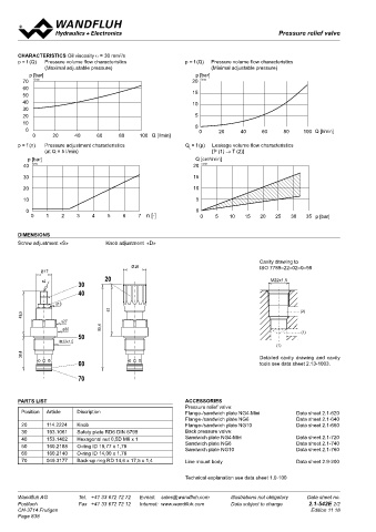
chaRacteRistics Oil viscosity υ = 30 mm /s
2
p = f (Q) Pressure volume flow characteristics p = f (Q) Pressure volume flow characteristics Pressure relief valve
(Maximal adjustable pressure) (Minimal adjustable pressure) screw-in cartridge M22x1,5
p [bar] p [bar] • Direct operated
70 K0106 20 K0104 • Q = 25 l/min Wandfluh standard
60 • p max = 400 bar
50 15 • p max = 350 bar
40 10 n max
30 DescRiPtion Function aPPlication
20 5 Direct operated pressure relief valve as a BX: If pressure in pilot line x reaches the set BX:
10 screw-in cartridge with a thread M22x1,5 and pressure poppet spool will be pushed against Used to pilot e.g.a logic elements wich must
0 0 0 20 40 60 80 100 Q [l/min] cavity according to Wandfluh-Norm. The valve the spring. Oil passage form P to T line will be relief independent of system pressure.
0 20 40 60 80 100 Q [l/min] is available in 2 different setting versions: Key opened-up irrespective of pressure in P line, BY:
setting „S“ and turning knob setting „D“. Key this due to a drain connection separating x Used to pilot e.g.a logic element with loading/
p = f (n) Pressure adjustment characteristics Q = f (p) Leakage volume flow characteristics adjustment „S“ is also available with cover and P line. Poppet spool and pilot piston are unloading and relief function in an accumulator
L
(at Q = 5 l/min) [P (1) → T (2)] see data sheet 2.0-50.2 standard pressure physically linked. or dual pump system.
3
p [bar] Q [cm /min] levels are available: 100 bar and 315 bar. The BY: If pressure in pilot line x reaches the set
40 K0103 20 K0105 cartridge body made of steel is galvanized and pressure poppet spool will be pushed against For machining the cavity in steel or aluminium
therefore rust-protected. the spring. Oil passage from P to T line will be tools are available for rent or sale. See also
30 15 opened-up. Poppet spool and pilot piston are data sheet in register 2.13
P(1) separate items. Due to the area ratio of the
20 10 pilot the required pilot pressure in x line is lower
than pressure in P line by the percentage of the
10 5 differential pressure.
0 0
T(2) 0 1 2 3 4 5 6 7 n [-] 0 5 10 15 20 25 30 35 p [bar] tYPe coDe
B PM22 - #
Pressure relief valve
DiMensions
Screw adjustment «S» Knob adjustment «D» Relief valve remote controlled X
Relief and unloading valve Y
Type of adjustment Key S
Cavity drawing to
Ø 26 ISO 7789–22–02–0–98 Control knob D
Ø 17 Cover A (see data sheet 2.0-50)
20
s4 M22x1,5
30 Screw cartridge M22x1,5
40 Nominal pressure range p 100 bar 100
s13 N 315 bar 315
57 (2) 350 bar 350
49,5
s27 Design-Index (Subject to change)
ø30 95,4 (1)
50 GeneRal chaRacteRistics hYDRaulic chaRacteRistics
M22x1,5 Description BX: Direct operated relief valve, Hydraulic fluid Mineral oils, other fluids on request
(1) remote controlled Max permissible ISO 4406:1999, class 18/16/13
38,4 Detailed cavity drawing and cavity BY: Direct operated relief valve, contamination level (recommended filter gauge ß 10…25≥75)
see data sheet 1.0-50/2
with additional unloading function
60 tools see data sheet 2.13-1003. Construction Screw-in cartridge for cavity acc. to Viscosity range 12 mm /s…320 mm /s
2
2
Wandfluh-standard Hydraulic fluid temp. -20…+70°C
70 Mounting M22x1.5 screw thread Peak pressure p max = 400 bar
Ambient temperature -20…+50°C p Tmax = p +20 bar
P
Installation position any Nominal pressure p = 100 bar, p = 315 bar, p = 350 bar
N
N
N
Tightening torque M = 50 Nm Min. pressure see characteristic
D
PaRts list accessoRies Weight: m = 0,20 kg (key) Differential pressure 11% for p = 100 bar
N
Pressure relief valve: m = 0,21 kg (control knob) (only for BY.PM22) 7,5% for p = 315 bar and p = 350 bar
N
Position Article Discription Flange-/sandwich plate NG4-Mini Data sheet 2.1-620 Volume flow Q = 0,1…25 l/min N
Flange-/sandwich plate NG6 Data sheet 2.1-640 Leak volume flow see characteristic (BX.PM22)
20 114.2224 Knob Flange-/sandwich plate NG10 Data sheet 2.1-660 tight seating (BY.PM22)
30 193.1061 Safety plate RD6 DIN 6799 Back pressure valve: sYMBols Mechanical actuation
40 153.1402 Hexagonal nut 0,5D M8 x 1 Sandwich plate NG4-Mini Data sheet 2.1-720 BX.PM22 BY.PM22 2 types of adjustments:
50 160.2188 O-ring ID 18,77 x 1,78 Sandwich plate NG6 Data sheet 2.1-740 S = Screw adjustment
Data sheet 2.1-760
Sandwich plate NG10
60 160.2140 O-ring ID 14,00 x 1,78 P(2) P(2) with fork wrench and Allen key
70 049.3177 Back-up ring RD 14,6 x 17,5 x 1,4 Line mount body Data sheet 2.9-200 D = Control knob adjustment, fixed
= 5 mm
Actuation stroke S
x(1) x(1) Actuation angle α b = 1800° (5 revolutions)
Technical explanation see data sheet 1.0-100 b
T(3) T(3)
Wandfluh AG Tel. +41 33 672 72 72 E-mail: sales@wandfluh.com Illustrations not obligatory Data sheet no. Wandfluh AG Tel. +41 33 672 72 72 E-mail: sales@wandfluh.com Illustrations not obligatory Data sheet no.
Postfach Fax +41 33 672 72 12 Internet: www.wandfluh.com Data subject to change 2.1-542E 2/2 Postfach Fax +41 33 672 72 12 Internet: www.wandfluh.com Data subject to change 2.1-544E 1/2
CH-3714 Frutigen Edition 11 18 CH-3714 Frutigen 17 ø 26 Edition 14 22
Ø
Page 838 20
s4 30
40
s13
47,1 54,6
s27
ø30
50
M22x1,5
53,5 70
60
75
65