
Page 729 - Softbound_Edition_19_en
P. 729
Amplifier and controller electronics
Amplifier / controller electronics
Controller electronics
CONSTRUCTION
General Fieldbus
• The „DSV“ electronics is an integral part of the valve. • The fieldbus is to be contacted through the corresponding device
• All inputs and outputs are to be contacted via the device receptacle. receptacle.
• Under the closing screw of the housing cover there is a USB - interface, • CANopen resp. Profibus DP is used as transmission protocol.
through which with the menu-controlled Windows program „PASO“ the • The characteristics and functions of the „DSV“ electronics are descri-
parameterisation and diagnostics can be carried out. bed through the device profile DSP-408 „Device Profile Fluid Power
• At the factory the “DSV” electronics are adapted to the valve, so that, Technology“. A detailed description can be found on our website (see
as a rule, no intervention of the user is necessary. set-up instructions).
• Via the fieldbus, the DSV electronics can be controlled and parame-
terised.
• The utilisation of J1939 has to be jointly specified by the customer
and Wandfluh.
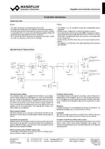
DESCRIPTION OF THE FUNCTION
HOLD
Command Solenoid output
value Solenoid
driver 1 Current measurement
Fieldbus only
Command
value 1 DigInp
Command Fixed Command
Command value command value Controller Valve
value 2 Scaling values generator type Enable Error
Solenoid output
DigInp DigInp DigInp DigInp Solenoid
driver 2
Selection Error Number Enable Solenoid 2 Current measurement
Command
value 1 Command DigInp
value
Scaling Enable Error
Display Window
Error
Command value scaling Feedback value scaling
The command value can be applied via the fieldbus or as a voltage, The feedback value can be applied as voltage, current, frequency or
current, digital, frequency or PWM signal. For every command value, PWM signal. For the feedback value, the input utilised can be selec-
the input utilised can be selected. The scaling takes place via the pa- ted. The scaling takes place via the parameters „Interface“ and „Refe-
rameters „Interface“ and „Reference“. Furthermore every command va- rence“. Furthermore the feedback value can be monitored for a cable
lue can be monitored for a cable break (except for digital signal). For break.
every command value a dead band can also be set. Optionally one can
operate with two command values. The characteristic of these com- Windows
mand values can be adjusted. A target, tracking error and magnetic stop window are available. The
threshold and delay time can be set for each window.
Fixed command values
One fixed command value is available, which can be selected via a di- Controller
gital input (only DSV electronics with analog interface and 12-pole con- The DSV controller module has a controller circuit. This is built up as
nector). PID controller. The following controller modes can be selected:
Command value generator Controler mode Pressure/flow valve control
With the Open-Loop-Controller modes, for each solenoid output two li- Control of a pressure relief, pressure reducing, throttle or flow control
near ramps for up and down are available which can be adjusted se- valve in open control circuit (without feedback value signal). The
parately. With the Cloded-Loop-Controller modes, a positive and a ne- number of solenoids that can be controlled depends on the selected
gative traversing speed is available. operating mode.
HOLD command value (fieldbus option only)
If via Profibus DP the device is put into the “HOLD” condition, the re-
spective command value is activated.
Wandfluh AG Tel. +41 33 672 72 72 E-mail: sales@wandfluh.com Illustrations not obligatory Data sheet no.
Postfach Fax +41 33 672 72 12 Internet: www.wandfluh.com Data subject to change 1.13-76E 9/10
CH-3714 Frutigen Edition 21 20
Page 729