Page 730 - Softbound_Edition_19_en
P. 730

5 6 7 8
                                                                                                                                                                                                       FUNCTION
                                                                                                                                                                                                      ERROR 1 2 3 4 SUPPLY  A B  A   B    99  105
                                                                                                                                                                                                          FIELDBUS X4
                                                                                                                                                                                                      USB
                                                                                                                                                                                                     9 10 11 12  C
                                                                                                                                                                                                     13 14 15 16  D
                                                                           Amplifier and controller electronics                                                                                          45   Digital amplifier module SD7
                                                                                                                                                                                                                                     C
                                                                                                                                                                                                                                  D
                                                                              Amplifier / controller electronics
                                                                                                                                                                                                                              114
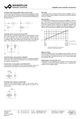
       Controler mode Pressure/flow valve control (1-Sol)»  Valve type                                                             Digital amplifier module SD7
       Actuation of one solenoid pressure relief, pressure reducing, throttle,   The operating mode is set here for the open loop controller modes. It   • For 1 or 2 proportional solenoids
       or flow control valve in closed-loop control circuit (with feedback value   is also possible to select whether proportional or switching solenoids
 P                                                                                                                                 • Interface:    - analog                                          1 2 3 4
       signal). Only one solenoid can be controlled with it (corresponds to   are to be controlled.                                                                                                  5 6 7 8          1 2 3 4            1 2 3 4
       the magnet driver 1).                                                                                                                      - CANopen / J1939                                                   5 6 7 8             5 6 7 8
  P           w
  Xi   DSV                                                  Solenoid driver                                                                       - Profibus DP
 x      P                     Q                             Two Pulse-Width-Modulated current outputs are available. To each out-
 P                                                          put, a dither signal is superimposed, whereas dither frequency and                    - HART
 t                                                                                                                                 • Max. 4 analog differential inputs                                FUNCTION
 Xi          P Xi  DSV    w   Q Xi      DSV    w            dither level can be adjusted separately. For each output, the minimum                                                                    ERROR  SUPPLY    ERROR  FUNCTION  SUPPLY  ERROR  FUNCTION  SUPPLY
 P  DSV  w  x                                               (Imin) and maximum (Imax) current can be adjusted separately. The      • Max. 8 digital inputs                                               FIELDBUS X4                          FIELDBUS X4
 Xi                                      Q                                                                                                                                                                               FIELDBUS X4
 x        Q                                                 solenoid outputs can also be configured as switching outputs. There-   • Fixed command values                                             USB
 DSV  t                                  Q                  with for each output a power reduction can be adjusted separately.                                                                       9 10 11 12       USB                  USB
                                                                                                                                                                                                                                          9 10 11 12
                                                                                                                                                                                                                      13 14 15 16
 t  Xi                                    Xi       DSV    w                                                                        • Adjustable via PC                                              13 14 15 16       9 10 11 12         13 14 15 16
 Xi       Q         DSV    w
 w        Xi                                                                                                                       • (optionally with manual operation on front panel)
 DSV                                                                                                                               • For snapping on to dome rail
 DSV                                                                                                                               • Also available as controller module (see data sheet 1.13-106)
 P                                                                                                                                                                                              A    B
 w     Controller mode „Pressure control (2-Sol)“
 w  V Xi  Control of two 1 solenoid throttle valves in closed position Control                                                                                         A
  P                                                                                                                                                                    B
  Xi   loop (with feedback value signal) as pressure reducing control.
 w     The one throttle valve serves as a loading valve and the other as                                                           DESCRIPTION                        FUNCTION                           APPLICATION
                                     P P
        P
 P  V  a unloading valve. The loading valve corresponds to the solenoid                                                            Digital amplifier module for installation on   The amplifier module has one, resp., two   As snap-on module, the amplifier module is
 Xi  DSV                                                                                                                           dome rail for controlling proportional or swit-  Pulse-Width-Modulated current outputs with   mainly utilised in the industrial field. The mo-
                                                DSV
             P
                                          P
 V     driver 1, the unloading valve corresponds to the solenoid driver 2.  w
             Xi
 Xi  DSV                                   Xi                                                      Command value                   ching valves with one or two solenoids. The   superimposed dither signal. The solenoid out-  dule can be mounted on dome-rails. The con-
 P  w
 Xi                        x                    P                      Q
 w  w            P                   P Xi                                                                                          parameterisation takes place by means of   puts can also be parameterised for switching  nection with terminal screws enables commis-
            DSV  t  Xi                                                Q         DSV     w            Analogue value                menu-controlled parameterisation and diagno- L  solenoids. The analog and digital inputs as well   sioning without special tools in a short time. The
 DSV  DSV  P                                                           Xi                                                          stics software «PASO» from Wandfluh (USB   as the digital outputs can be programmed in-  amplifier module is particularly suitable for ap-
 DSV                                DSV                                                                                            interface) or optionally with a manual opera-  dividually. With this device control tasks can be   plications with additional functions such as
             w                                  P Xi                 Changing over between the two solenoids
 w               P DSV                                               by means of the selected digital input                        tion on the front panel. Separate ramps for up   solved in a very simple manner. The fieldbus   ramps, fixed command values, etc. Customer
                 Xi                  w                                                                                             and down as well as fixed adjustable command   connection enables reading the command va-  specific requirements can be implemented in a
 w      P                                                                                                                                                              C
 Xi              w                              DSV                                                                                values are integrated in the amplifier module   lue signal as well as the parameterisation di-  simple manner.
 P  t                                                                                                                                                                  D
 Xi             DSV                                         Signal recording                                                       as standard.  The electronics are optionally   rectly via the fieldbus.
 DSV                                            w           The DSV controller module has a signal recording function. This, by    available with different fieldbus interfaces.                C    D
 w                                                          means of PASO, enables the recording of various system signals, such
 Xi  DSV         w                    P
 w         t                                                as command value, solenoid currents, etc., which can be represented
            Xi
                 V
 Xi  t  Controller mode „Axis position controlled“
                  Xi
 Xi                                       P                 on a common time axis.
 DSV  w  Control of a spool valve in the open control circuit (without feedback
                                           Xi
 DSV   value signal). The number of solenoids to be controlled depends on   Optimisation of characteristic curve                   GENERAL SPECIFICATIONS
                       w
                                                                              P
           DSV
 DSV   the selected operating mode.      DSV                A characteristic curve adjustable per solenoid „Command value input    Execution              Module for control cubicle,
                                                                                                                                                          housing made of plastic

           w         DSV                                    – solenoid current output“ enables an optimised (e.g., linearised) char-
 w     Control mode „Axis position controlled (2-Sol)“      acteristic of the hydraulic system.
                                          w
       Control of a two solenoid spool valve in closed position control loop   P Xi                                                Installation           on 35 mm dome rail according to
       (with feedback value signal). Two solenoids can be used with it.                                                                                   EN 60715
                                     P                                                                                             Weight
                                                                             DSV                                                   • Basic amplifier analog    130 g
                                     P                                                                                             • Basic amplifier fieldbus    220 g
                                                                              w                                                    • Enhanced amplifier analog    220 g
                       w
                 Xi                       P     DSV    w                                                                           • Enhanced amplifier fieldbus   240 g
                                        t  Xi
                           x             Xi                            Q
                     DSV                                                                                                           Connections            Screw terminals,
                 t
                 Xi                     DSV                           Q Xi      DSV     w                                                                 max. cable cross-section 2,5 mm²
                                                                                                                                   Working temperature    -20…+70 °C
                DSV                      w
       Controller mode „Speed control (2-Sol)“
       Control of  a two  solenoid  spool,  throttle,  or  flow  control  valve  in                                                Further information can be found in the Operating instructions.
                 w
       closed control loop (with feedback value signal). Two solenoid can
       be used with it.
                                      P
                 V
                  Xi
                                          P
                                           Xi                                                                                      COMMISSIONING                                         ADDITIONAL INFORMATION
                       w                                                      P
                                                                                                                                   Information regarding installation and commissioning are contained in                Wandfluh documentation
                                         DSV                                                                                       the information leaflet supplied with the amplifier module and in the Ope-  Wandfluh electronics general    Register   1.13
                     DSV                                                                                                           rating instructions. Further information can be found on our website:   Proportional spool valves    Register   1.10
                                                                                                                                   www.wandfluh.com                                      Proportional pressure valves    Register   2.3
                                          w                                  P
                                                                              Xi                                                                                                         Proportional flow valves       Register   2.6
                                                                                                                                   Free-of-charge download:
                                     P
                                                                             DSV                                                   • «PASO» Parameterisation software
                                                                                                                                   • Operating instructions (.pdf)
                                                                                                                                   • Device description data:    (EDS file «WAGSD7C1.eds»)
                                                                              w
                       w                                                                                                                                 (GSD file «SD7-0B8E.gsd»)
                 Xi                     t
                                         Xi
                     DSV
                                        DSV
       Wandfluh AG        Tel.  +41 33 672 72 72   E-mail:  sales@wandfluh.com   Illustrations not obligatory   Data sheet no.     Wandfluh AG         Tel.  +41 33 672 72 72   sales@wandfluh.com     Illustrations not obligatory   Data sheet no.
                                         w
       Postfach           Fax  +41 33 672 72 12   Internet:  www.wandfluh.com   Data subject to change   1.13-76E 10/10            Postfach            Fax  +41 33 672 72 12   www.wandfluh.com        Data subject to change   1.13-101E 1/10
       CH-3714 Frutigen                                                                            Edition 21 20                   CH-3714 Frutigen                                                                             Edition 23 02
       Page 730
   725   726   727   728   729   730   731   732   733   734   735