
Page 733 - Softbound_Edition_19_en
P. 733
Digital amplifier module SD7 Digital amplifier module SD7
Digital amplifier module
ELECTRICAL SPECIFICATIONS
Protection class IP 30 according to EN 60 529 Fieldbus (option)
TYPE CODE Supply voltage 24 VDC or 12 VDC
S D7 - # Voltage range: • Device receptacle DSUB, 9-pole, CANopen, J1939, Profibus
• 24 VDC 21…30 V • Screw terminals HART
Control cubicle • 12 VDC 10,5…15 V • Bus topology Line, differential signal transmission
Residual ripple <10 % • Potential separation 500 VDC
Digital Fuse Low
Adjustable with Current consumption: Solenoid current:
• PASO and manual operation (Basic amplifier only, without fieldbus) 2 • No-load current approx. 40 mA • Minimal current I Adjustable 0…950 mA
min
• PASO without manual operation 3 • Maximum current Factory setting 150 mA
consumption No-load current + 1,8 A
Software configuration (function of card): per solenoid (with 24 VDC) • Maximal current I max Adjustable I …1,8 A (with 24 VDC)
min
I …2,3 A (with 12 VDC)
min
• Basic amplifier 0 No-load current + 2,3 A Factory setting 700 mA
• Enhanced amplifier 5 per solenoid (with 12 VDC) • Accumulated current
1-solenoid version 1 Command value signal: Selectable by means of software limitation The accummulated current of the simulta-
2-solenoid version 2 Input 1 and 2 neously controlled solenoids depends on the
ambient temperature. Further information can
Supply voltage: 24 VDC D2 Differential input not galvanically separated, be found in the Operating instructions.
for ground potential difference up to 1,5 V
12 VDC D3 Dither Frequency adjustable 20…500 Hz
4…+20 mA / 0…+20 mA Factory setting 100 Hz
Basic amplifier: 0…+10 V (1- or 2-solenoid version) Level adjustable 0…400 mA
• Analog input 1: voltage 0 -10…+10 V (2-solenoid version only) Factory setting 100 mA
2: current Input 3 (option): Temperature drift <1 % at ΔT = 40 °C
• Analog input 1 and 2: both voltage 1 Galvanically separated for HART signal Digital inputs Switching threshold high 6…30 VDC
• Analog input 1 and 2: both current 2 Resolution 10-bit (analog inputs 1 and 2) Switching threshold low 0…1 VDC
Analog input 3: always current (with HART only) Input resistance 16-bit (analog inputs 3 and 4) Digital input 5 – 7 can be used as frequency
Voltage input >18 kΩ
input (frequencies 0…5 kHz) and as PWM
Enhanced amplifier: Load for current input = 250 Ω input (automatic frequency recognition)
• Analog input 1 and 3: both voltage 4 Analog output Enhanced amplifier: Digital outputs Low-Side-Switch:
Analog input 2 and 4: both current Voltage output ± 10 VDC U max = 40 VDC
Max. output current ± 3 mA
• Analog input 1 to 4: all voltage 5 Enhanced amplifier with HART: I max = -700 mA
• Analog input 1 to 4: all current 6 Current output 0…20 mA Ramps adjustable 0…500 s
• Analog input 1 and 2: both voltage 7 Max. output voltage 12 VDC Serial interface USB (plug type B)
Analog input 3 and 4: both current for parameterising with «PASO»
• Analog input 1 and 2: both current 8 Stabilised output 10 VDC (with 24 VDC) EMV
Analog input 3 and 4: both voltage voltage 8 VDC (with 12 VDC) Immunity EN 61 000-6-2
Emission
EN 61 000-6-4
Analog input 3 and 4: always current (with HART only) Max. load 30 mA
Basic amplifier without HART
• Analog input 1 and 2: 10-bit resolution A
Basic amplifier with HART
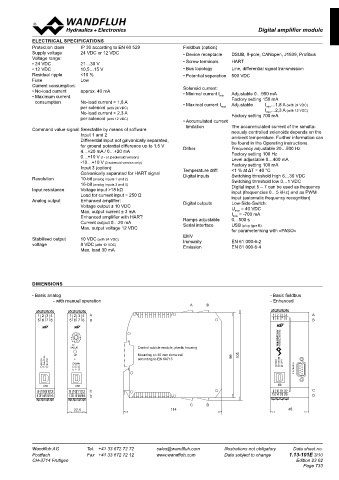
• Analog input 1 and 2: 10-bit resolution B DIMENSIONS
• Analog input 3: 16-bit resolution
Enhanced amplifier - Basic analog - Basic fieldbus
• Analog input 1 and 2: 10-bit resolution B - with manual operation - Enhanced
• Analog input 3 and 4: 16-bit resolution A A B B A B
Option fieldbus: A A 1 2 3 4 A
• without fieldbus A B B 5 6 7 8 B
• with CANopen C
• with Profibus DP P
• with J1939 J
• with HART H
Control cubicle module, plastic housing
Design-index (Subject to change) Mounting on 35 mm dome rail 105
L L according to EN 60715 FUNCTION 99
ERROR SUPPLY
FIELDBUS X4
USB
C C 9 10 11 12 C
D D 13 14 15 16 D
D C
C C D D
45 114
Wandfluh AG Tel. +41 33 672 72 72 sales@wandfluh.com Illustrations not obligatory Data sheet no. Wandfluh AG Tel. +41 33 672 72 72 sales@wandfluh.com Illustrations not obligatory Data sheet no.
Postfach Fax +41 33 672 72 12 www.wandfluh.com Data subject to change 1.13-101E 2/10 Postfach Fax +41 33 672 72 12 www.wandfluh.com Data subject to change 1.13-101E 3/10
CH-3714 Frutigen Edition 23 02 CH-3714 Frutigen Edition 23 02
1 2 3 4 Page 733
5 6 7 8
1 2 3 4 1 2 3 4
5 6 7 8 5 6 7 8
ERROR FUNCTION SUPPLY
FIELDBUS X4 ERROR FUNCTION SUPPLY ERROR FUNCTION SUPPLY
FIELDBUS X4 FIELDBUS X4
USB
9 10 11 12 USB USB
13 14 15 16 9 10 11 12 9 10 11 12
13 14 15 16 13 14 15 16