Page 1126 - Softbound_Edition_19_en
P. 1126

Throttle valve
                                                                                               Throttle valves                                                                                                             Throttle valves


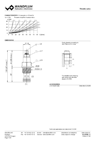
       CHARACTERISTICS  Oil viscosity υ = 30 mm /s                                                                                 Throttle valve
                                       2
       ∆p = f (Q)   Pressure drop/flow characteristics                                                                             Screw-in cartridge                             M33x2
          p [bar]                                                                                                                  •  Q N max  =  140 l/min                       ISO 7789
        40  K4037  0,5  1     1,5   2     2,5                                                                                      •  Q    =  140 l/min
                                              3                                                                                    •  p max   =  350 bar
        30                                    3,5                                                                                     max
                                              4
        20                                    4,5
                                                                                                                                   DESCRIPTION                        FUNCTION                           APPLICATION
        10                                                                                                                         Manually adjustable, M33x2 screw-in cart-  A fine tread on the adjustable throttle reveals   Throttle valves can be used anywhere where
                                                                                                                                   ridge throttle valve in accordance with cavity   an annular gap. The adjusted throttle cross-  volume flows can be infinitely controlled in both
         0
           0   10  20  30  40   50  60  70  80  Q [l/min]                                                                          ISO 7789. The cartridge body made of steel is   section produces a pressure drop which de-  directions without taking pressure fluctuations
                                                                                                                                   galvanized and therefore rust-protected.  termines the volume flow. The volume flow is   into account. Stepped tools are available for
                                                                                                                                                                      zero when the throttle is screwed in (the metal   making the receptacle bores in steel and alu-
                                                                                                                                                                      sealing edge seals completely). The valve flow   minium (hire or purchase). Please refer to the
       DIMENSIONS                                                                                                                                                     is bidirectional.                  data sheets in register 2.13.
                                 18              s4                        Cavity drawing according to
                                                                           ISO 7789–22–01–0–98


                                                 s17                          M22x1,5                                                                                 TYPE CODE
                44 (48 max.)                     s24                                    (2)                                                                             Throttle valve                          DN   I   PM33   -   140  #


          83 (87 max.)                     M22x1.5                              (1)     (1)                                                                           Screw-in cartridge M33x2  N        140 l/min
                                                                                                                                                                      Type of adjustment
                                            Ø28
                                                                                                                                                                      Nominal volume flow rate Q
                                                                                                                                                                      Design-Index (Subject to change)

                39                    (2)                                  For detailed cavity drawing

                                                                           and cavity tools see data
                                                                           sheet 2.13-1008.

                               (1)                          ACCESSORIES
                                                            Line mount body                    Data sheet 2.9-205                  GENERAL SPECIFICATIONS                               HYDRAULIC SPECIFICATIONS
                                                                                                                                   Description           Throttle valve                 Fluid               Mineral oil, other fluid on request
                                                                                                                                   Construction          Screw-in cartridge for cavity   Contamination efficiency   ISO 4406:1999,
                                                                                                                                                         acc. to ISO 7789                                   class 20/18/14…21/19/15
                                                                                                                                   Mounting              Screw-in thread M33x2                              Required filtration grade (ß 10…25 ≥ 75)
                                                                                                                                   Ambient temperature   -20…+50 °C                                         (refer to data sheet 1.0-50/2)
                                                                                                                                   Mounting position     any                            Viscosity range     12mm /s…320mm /s
                                                                                                                                                                                                                         2
                                                                                                                                                                                                                 2
                                                                                                                                   Fastening torque      M  = 80 Nm                     Fluid temperature   -20…+70 °C
                                                                                                                                                          D
                                                                                                                                   Weight                m = 0,37 kg                    Peak pressure       p max  = 350 bar
                                                                                                                                   Volume flow direction   1 ↔ 2                        Nominal volume flow rates  Q   = 140 l/min
                                                                                                                                                                                                              N
                                                                                                                                                                                                            Q  at 10 bar valve pressure loss
                                                                                                                                                                                                             N
                                                                                                                                                                                        Max. volume flow    Q max = 140 l/min
                                                                                                                                                                                        Leakage volume flow   Almost leak free with closed restrictor
                                                                                                                                   SYMBOL
                                                                                                                                                                                        MECHANICAL ACTUATION
                                                                                                                                       1         2                                      Screw adjustment with fork wrench and Allen key
                                                                                                                                                                                        Control storke S    b        =  4,5 mm
                                                                                                                                                                                        Control angle α          =  1620° / 4,5 turns
                                                                                                                                                                                                   b

                                                                                                                                      s 4

                                                            Technical explanation see data sheet 1.0-100

       Wandfluh AG        Tel.  +41 33 672 72 72   E-mail:  sales@wandfluh.com   Illustrations not obligatory   Data sheet no.     Wandfluh AG         Tel.  +41 33 672 72 72   E-mail:  sales@wandfluh.com   Illustrations not obligatory   Data sheet no.
                                                                                                                                      s 19
       Postfach           Fax  +41 33 672 72 12   Internet:  www.wandfluh.com   Data subject to change   2.4-532E 2/2              Postfach            Fax  +41 33 672 72 12   Internet:  www.wandfluh.com   Data subject to change   2.4-552E 1/2
       CH-3714 Frutigen                                                                            Edition 21 40                 (max. 45)  CH-3714 Frutigen                                                                    Edition 11 26
       Page 1126                                                                                                                      s 30
                                                                                                                                 38.75


                                                                                                                          88.8        M33 x 2


                                                                                                                                 50.05


                                                                                                                                                     Ø 39
   1121   1122   1123   1124   1125   1126   1127   1128   1129   1130   1131