
Page 1129 - Softbound_Edition_19_en
P. 1129
Throttle valve
Throttle valves Restrictor valve
Throttle non-return cartridge
2
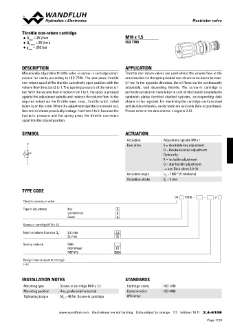
CHARACTERISTICS Oil viscosity υ = 30 mm /s Q = 25 l/min M18 x 1,5
∆p = f (Q) Pressure drop/flow characteristics ◆ Q max = 25 l/min ISO 7789
p [bar] ◆ N max
40 K4036 0,5 1 1,5 2 ◆ p = 350 bar
max
30 2,5
20 3
3,5
4 DESCRIPTION APPLICATION
10 4,5
Mecanically adjustable throttle valve in screw-in cartridge const- Throttle non-return valves are used where the volume flow in the
0 ruction for cavity according to ISO 7789. The one-piece throttle one direction via the spring loaded non-return valve has to be near-
0 20 40 60 80 100 120 140 Q [l/min]
1 2 non-return spool shifts into the completely open position with the ly free. In the opposite direction, the oil flows via the continuously
volume flow direction 2 to 1. The opening pressure of the valve is 1 adjustable, load depending throttle. The screw-in cartridge is
DIMENSIONS bar. With the volume flow direction from 1 to 2, the spool is pressed perfectly suitable for installation in control blocks and is installed in
against the adjustment spindle and reduces the volume flow to the sandwich plates (vertical stacked systems, corresponding data
Cavity drawing according to
s 4 ISO 7789–33–01–0–98 required extent via the throttle area, resp., throttle notch, milled sheets in this register). For machining the cartridge cavity in steel
laterally on the cone. When the adjustment spindle is screwed out, and aluminum blocks, cavity tools are available (hire or purchase).
the throttle closes practically leakage-free from 1 to 2, because the Please refer to the data sheets in register 2.13.
M33x2 hydraulic pressure and the spring press the throttle non-return
spool into the closed position.
s 19
(max. 45) s 30 (2) SYMBOL ACTUATION
38.75 (1) 2 Actuation Adjustment spindle M8 x 1
Execution
S = blockable key adjustment
D = blockable knob adjustment
88.8 M33 x 2 (1) Optionally:
K = lockable adjustment
1 G = star handle adjustment
50.05 Actuation angle → see Data sheet 2.0-50
a = 1800 ° (5 rotations)
For detailed cavity drawing
b
and cavity tools see data Actuation stroke S = 5 mm
b
sheet 2.13-1005.
TYPE CODE
ACCESSORIES DR PM18 - - #
Ø 39 Line mount body Data sheet 2.9-205 Throttle non-return valve
Type of adjustment Key S
Control knob D
Cover A
Screw-in cartridge M18 x 1,5
Nominal volume flow rate Q N 3,2 l/min 3,2
25 l/min 25
Sealing material NBR
FKM (Viton) D1
NBR 872 Z604
Design index (subject to change)
2.4-610
INSTALLATION NOTES STANDARDS
Mounting type Screw-in cartridge M18 x 1,5 Cartridge cavity ISO 7789
Mounting position Any, preferably horizontal Contamination ISO 4406
Tightening torque M = 40 Nm Screw-in cartridge efficiency
Technical explanation see data sheet 1.0-100 D
Wandfluh AG Tel. +41 33 672 72 72 E-mail: sales@wandfluh.com Illustrations not obligatory Data sheet no.
Postfach Fax +41 33 672 72 12 Internet: www.wandfluh.com Data subject to change 2.4-552E 2/2 www.wandfluh.com Illustrations are not binding Data subject to change 1/3 Edition: 19 11 2.4-610 E
CH-3714 Frutigen Edition 11 26
Page 1129