
Page 1121 - Softbound_Edition_19_en
P. 1121
Throttle valve
Throttle valve
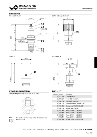
DIMENSIONS
Key adjustment „S” Control knob adjustment „D”
17 s3 27
30
40
s10
39.5 s19 47 20
68.5 Ø23 76
M18x1.5 50
29 2(T)
60
1(P) 70
Cover „A” Star handle „G”
23 40
44.6 25 55 26
73.6 84
HYDRAULIC CONNECTION PARTS LIST
Cavity drawing according to ISO 7789–18–01–0–98 Position Article Description
20 114.2228 Control knob K9
M18x1.5
25 032.0616 Cover rd 23 / 3 x 35 K9
26 082.2004 Star handle rd 40 x 26
30 193.1042 Retainer stainless rd 4 DIN 6799
(2)
40 153.1303 Hexagon nut 0,5d A4 M6 x 3,2
45 234.1060 Washer DIN 125A M6
(1)
50 160.2156 O-ring ID 15,60 x 1,78 (NBR)
160.6156 O-ring ID 15,60 x 1,78 (FKM)
(1)
60 160.2111 O-ring ID 11,11 x 1,78 (NBR)
160.6111 O-ring ID 11,11 x 1,78 (FKM)
Note! For detailed cavity drawing and cavity tools see data
sheet 2.13-1002 70 049.3156 Backup ring rd 12,1 x 15 x 1,4
www.wandfluh.com Illustrations are not binding Data subject to change 3/4 Edition: 19 39 2.4-510S E
Page 1121