
Page 1117 - Softbound_Edition_19_en
P. 1117
Throttle valve
Throttle valve
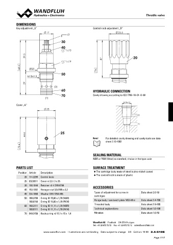
DIMENSIONS
Key adjustment „S” Control knob adjustment „D”
17 25.5
s3
30
40
s10
39.5 20
s19 47
68.5 Ø23
50 76
M18x1.5
29
(2)
60 HYDRAULIC CONNECTION
70 Cavity drawing according to ISO 7789–18–01–0–98
(1)
M18x1.5
Cover „A”
23
(2)
(1)
44.6 25 (1)
Note! For detailed cavity drawing and cavity tools see data
sheet 2.13-1002
73.6
SEALING MATERIAL
NBR or FKM (Viton) as standard, choice in the type code
PARTS LIST SURFACE TREATMENT
Position Article Description ◆ The cartridge body made of steel is zinc-nickel coated
◆ The control knob is made of plastic
20 114.2299 Control knob
25 032.0611 Cover rd 23 / 3 x 35
30 193.1040 Retainer rd 4 DIN 6799 ACCESSORIES
40 153.1302 Hexagon nut 0,5d M6 x 3,2
45 234.1060 Washer DIN 125A M6 Types of adjustment for screw-in Data sheet 2.0-50
cartridges
50 160.2156 O-ring ID 15,60 x 1,78 (NBR)
160.6156 O-ring ID 15,60 x 1,78 (FKM) Flange body / sandwich plate NG3-Mini Data sheet 2.4-700
60 160.2111 O-ring ID 11,11 x 1,78 (NBR) Threaded body Data sheet 2.9-205
160.6111 O-ring ID 11,11 x 1,78 (FKM) Technical explanations Data sheet 1.0-100
70 049.3156 Backup ring rd 12,1 x 15 x 1,4 Filtration Data sheet 1.0-50
Wandfluh AG Postfach CH-3714 Frutigen
Tel. +41 33 672 72 72 Fax +41 33 672 72 12 sales@wandfluh.com
www.wandfluh.com Illustrations are not binding Data subject to change 3/3 Edition: 19 09 2.4-510 E
Page 1117