
Page 1113 - Softbound_Edition_19_en
P. 1113
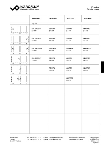
Overview
Proportional Over-view
pressure reducing valves Throttle valves
Throttle valves
1 2
1
2
1
2
2
1
2
1
SCREw-IN CaRTRIDGES INSTallED REMaRK! 1 2
The following screw-in cartridges are used in either the flange body Detailed performance data and additional hy-
or the sandwich body: draulic and electric specifications may by drawn NG3-Mini NG4-Mini NG6 ISO NG10 ISO
Type Designation Data sheet no. Q max * from the data sheets of the corresponding A PT B
A
PT
B
A
MVPPM22 pilot operated 2.3-629 60 l/min installed screw-in cartridge. A PT B
B
PT
PT
B
A
MQPPM22 pilot operated from connection P 2.3-641 40 l/min A PT B Types
MVBPM22 pilot operated, explosion proof Ex d 2.3-635 60 l/min CaUTION! 1 2
2
1
1
1
2
MVVPM22 pilot operated, with integrated electronics 2.3-632 60 l/min The performace data especially the „pressure- 2
2
1
1
MQVPM22 pilot operated from connection P, 2.3-643 40 l/min flow-characteristic„ on the data sheets of 2 DN.SA03-A BDRA4 ADRA6 ADRA10
with integrated electronics the screw-in catridges refere to the screw-in A PT B 2.4-700 A PT 2.4-730 2.4-750 2.4-770
B
B
A
PT
A
B
PT
cartridges only. The additional press-ure drop A PT B A PT B
B
PT
PT
A
A
B
A
B
B
PT
PT
A
of the flange body respectivly sandwich body A PT B A PT B
must be taken into consideration.
* Can deviate from the values on the data sheets of the scew-in cartridges. ** Do not use anymore for new applications. P T DN.SA03-B BDRB4 ADRB6 ADRB10
P
T
P
T
T
P
TyPE lIST / FUNCTION P T 2.4-700 2.4-730 2.4-750 2.4-770
P
T
PT
B
PT
B
A
A
Flange construction: Sandwich construction: B A P T 54 B 20 A PT B A PT B
A
A
B
PT
B
PT
PT
PT
A
B
A
B
T
A
P red.
P T
A
B
PT
A
PT
A
B
32,5 10 B 48 A PT B A PT B
A P red. T B A P T B A P T 20,8 B
P DN.SA03-AB BDRAB4 ADRAB6 ADRAB10
∗ 1,5 A B G1/4"
46 26,5 60 2.4-700 2.4-730 2.4-750 2.4-770
A
PT
B
B
PT
A
A P T B A P T B A red. P T B 39 A T P T B red. 32,5 A PT B A PT B
B
PT
A
PT
A
B
To
PT
PT
B
A
A
B
B
A
A
PT
B
PT
A P T B A PT B A PT B
10,5
6,5
A P T B A red. P T B A P T B red.
Ø Ø 6 44 95 45
MV.FA10-P/a MV.SA10 - P MV.SA10 - a 50 MV.SA10 - B140 DN.SA03-P BDRP4 ADRP6 ADRP10
A P red. T B A P T B A P T B 2.4-700 2.4-730 2.4-750 2.4-770
PT
B
A
PT
B
A P red. T B A P T B A P T B A PT B A PT B
A
PT
B
A
B
PT
A
PT
B
A
B
PT
A
A
PT
B
PT
B
A
32 A PT B A PT B
P
∗ G1/4" BDRT4 ADRT6 ADRT10
A P T B A red. ♦ P T ♦ A B 60 2.4-730 2.4-750 2.4-770
A P T B A P T B B 40 A T P T B red. 42,5 A PT B A PT B
To
A red.
A
A
A
A
B
MQ.FA10-P/a MQ.SA10 - P P T B MQ.SA10 - a P T B MQ.SA10 - B P T B red. A PT B A PT B
PT
PT
B
B
A
PT
B
PT
A
B
B
PT
A
A
PT
6,5 50 95 45 A PT B A PT B
DIMENSIONS Ø 140 ADRPT6
Flange construction Sandwich construction in A or B 2.4-750
10 54 20
32,5 48 54 20 18 A PT B A PT B
PT
B
A
A
B
PT
B
A
PT
A
PT
B
32,5 10 20,8 16 A PT B A PT B
48
PT
A
B
B
PT
A
20,8 A PT B A PT B
P P
∗ 1,5 A P B G1/4" ∗ A B G1/4"
∗ 46 26,5 B 60 ♦ ♦ 60
39 46 26,5 1,5 T A To G1/4" 32,5 60 40 T To 42
39 T To 32,5
10,5 6,5 6,5
10,5 6 6,5 Ø 93,5 46,5
Ø Ø 44 95 45 50
Ø Ø 50 44 95 140 45 140
6
50 140
Sandwich construction in P For sandwich red. pressure in B cartridge is located on B-side.
32
32
P
∗ A P B G1/4"
♦ ♦ ∗ A B G1/4" 60
♦ ♦ 40 T To 42,5 60
40 T To 42,5 ∗ The envelop dimensions of the screw-in cartridge are shown on
6,5 50 95 45 their corresponding data sheets.
Ø
6,5 50 95 140 45
Ø ♦ Distance plate ADP10/... must be ordered separatly.
140
PaRTS lIST 18 aCCESSORIES
16 Proportional amplifier register 1.13
18
Position Article Description P
16
∗ G1/4" Distance plate ADP10/29,5 (29,5 mm) art. no. 173.4456
10 ♦ 160.2140 O-ring ID 14,00 x 1,78 (NBR) B G1/4"
P
A
∗
♦
20 ♦ 238.2406 40 Plug VSTI G1/4"-ED T A B To 42 60 60
♦
40 T To 42
6,5 50 Technical explanation see data sheet 1.0-100
Ø 93,5 46,5
6,5 50 140
93,5
46,5
Wandfluh AG Tel. +41 33 672 72 72 E-mail: sales@wandfluh.com Illustrations not obligatory Data sheet no. Wandfluh AG Tel. +41 33 672 72 72 E-mail: sales@wandfluh.com Illustrations not obligatory Data sheet no.
Ø
140
Postfach Fax +41 33 672 72 12 Internet: www.wandfluh.com Data subject to change 2.3-860E 2/2 Postfach Fax +41 33 672 72 12 Internet: www.wandfluh.com Data subject to change 2.4-502E 1/2
CH-3714 Frutigen Edition 14 04 CH-3714 Frutigen Edition 21 31
Page 1113