Page 1110 - Softbound_Edition_19_en
P. 1110

Proportional                                                                                                                 Proportional
                                                                         Proportional pressure reducing valve                                                                                                     pressure reducing valves
                                                                                     pressure reducing valves

       SCREw-IN CaRTRIDGES INSTallED                                        REMaRK!                                                Proportional pressure reducing valve            NG10
       The following screw-in cartridges are used in either the flange body or the sandwich body:  Detailed performance data and additional hy-  Flange and sandwich construction
       Type        Designation                 Data sheet no.  Q max *      draulic and electric specifications may by drawn       •  p  = 400 bar                              ISO 4401-05
       MVPPM22     pilot operated              2.3-629     60 l/min         from the data sheets of the corresponding                 max
       MQPPM22     pilot operated from connection P   2.3-641   40 l/min    installed screw-in cartridge.
       MVBPM22     pilot operated, explosion proof Ex d   2.3-635   60 l/min
       MVPPM22-../ME pilot operated, with integr. electronics  2.3-632   60 l/min
       MQPPM22-../ME pilot operated from connection P,   2.3-643   40 l/min  CaUTION!
                   with integrated electronics                              The performace data especially the «pressure-
                                                                            flow-characteristic» on the data sheets of
                                                                            the screw-in catridges refere to the screw-in
                                                                            cartridges only. The additional press-ure drop
                                                                            of the flange body respectivly sandwich body
       * Can deviate from the values on the data sheets of the screw-in cartridges.
       ** Do not use anymore for new applications.                          must be taken into consideration.
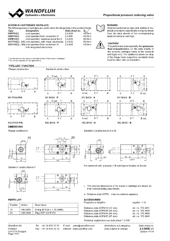
       TyPE lIST / FUNCTION
       Flange construction:      Sandwich construction:                                                                            DESCRIPTION                        FUNCTION                           aPPlICaTION
                                  A  P red.  T    B        A       P T      B        A      P T      B                             Pilot operated proportional pressure reducing   By adjusting the electric current to the propor-  The valves have their applications in hydraulic
                                  A  P red.  T    B         A      P T      B        A       P T      B                            valves NG10. Flange and sandwich construct-  tional solenoid the pressure in the controlled   systems in which the pressure in a consumer
                                                                         10                    21,5  19  20                        ion according to ISO 4401-05 with 4 ports.   port will be changed proportionally to the sole-  has to remain constant at the adjusted value
                                                                     22,5                        17,8                              Incorporated are proportional pressure reduc-  noid current. A pressure rise in the controlled   independently of pressure fluctuations on the
                                                                                                                                   ing cartridges size M22x1,5 according to ISO   port above the adjusted value, caused e.g.   supply side. The facility for remote control and
                                                                                                                                   7789. The steel bodies for flange constructions   by an active oil consumer, will be prevented   signal processing from process control systems
        A       P T      B        A      P T      B       A red.   P T      B    ∗               T  B   G1/4"                      are painted with a two component  painting   by reliefing excessive flow to the tank line T.   enable economical solutions to problems with
        A       P T      B                                                           A   31  21  P T A  B red.  32,5  45           and the bodies for sandwich constructions are   This proportional pressure reducing valves   repeatable sequences.
                                  A       P T     B        A red.  P T      B        A       P T  P  B red.                        phosphatized.                      are adjustable very sensitivly. To control the
       MV.FA06-P/a               MV.SA06 - P              MV.SA06 - a              MV.SA06 - B            22,5                                                        valve proportional amplifiers are available from
                                                              5,5
                                                             9,5
                                                                     42
                                  A  P red.  T     B       A  Ø  Ø  3  P T  B        A     85 P T   38 B                                                              Wandfluh (see register 1.13).
                                                                                              123
                                                                    45
                                  A  P red.  T     B        A      P T      B        A       P T     B
                                                                                                                                   TyPE CODE
                                                                      18,5                                                                                                               M           A10  -     -                    #
        A       P T      B                                A red.   P T      B                    T                                 Pressure reducing valve
                                                                                                    B
        A       P T      B        A       P T      B            ♦       ♦        ∗   A      P T A   B red.  G1/4"  45
                                                           A red.
                                  A
                                                                                     A
       MQ.FA06-P/a               MQ.SA06 - P P T   B      MQ.SA06 - a P T   B      MQ.SA06 - B P T  P  B red.  16,4                2nd and 3rd digit position of the designation od the built-in cartridge
       DIMENSIONS                                            5,5                                                                   Flange construction                  F
                                                             Ø       27,5                  85       38                             Sandwich construction                S
       Flange construction                                  Sandwich construction in A or B   123
                                                                    40
                                                                                                                                   International standard interface ISO, NG10
                    10                    21,5  19  20                                                                             Type list / Function   flange construction    sandwich construction
                22,5                        17,8                      18                                                                                  P → A         P/A      in P          P
                                                                                                                                                                                 in A          A
                                            T                                                    T                                                                               in B          B
                            ∗             A    B   G1/4"                                       A    B   G1/4"
                                   31  21              32,5  45  ♦      ♦        ∗                          45                     Nominal pressure range, nominal voltage, etc., of the built-in cartridge
                                            P                                 18,5               P        16,5                     Design-Index (Subject to change)
       9,5  5,5                                      22,5    5,5         12,5            88  88     37
       Ø  Ø  3  42                    85       38            Ø      50                      125 125
               45                        123
                                                            For sandwich red. pressure in B cartridge is located on B-side.        Examples:  M V P F A10 – P/A – 100 – G24 / WD – D1
       Sandwich construction in P                                                                                                           M V B S A10 – A –  200 – G12 / L15 / IN
                18,5                                                                                                                        M Q P S A10 – B –  350 – G24 / MEA1 – HB0
                                            T
           ♦       ♦        ∗             A    B   G1/4"  45
                                            P        16,4
                                                                                                                                   GENERal SPECIFICaTIONS
        5,5                                                 ∗  The envelop dimensions of the screw-in cartridge are shown on       Description        Pilot operated proportional
        Ø       27,5                  85       38              their corresponding data sheets.
               40                        123                                                                                                          pressure reducing valve
                                                                                                                                   Nominal size       NG10 according to ISO 4401-05
                                                            ♦  Distance plate ADP6/... must be ordered separatly.                  Constructions      Flange or sandwich
                 18                                                                                                                Operations         Proportional solenoid
       PaRTS lIST                                           aCCESSORIES                                                            Mounting           4 fixing holes for socket head cap screws
                                                            Proportional amplifier            register  1.13                                          M6 or studs M6
        Position   Article   Description  A  T  B                                                                                  Connections        Threaded connection plates
          ♦        ♦        ∗                      G1/4"  45  Distance plate ADP6/12 (12 mm)   art. no. 173.3451
        10      160.2093   18,5  O-ring ID 9,25 x 1,78 (NBR)  16,5  Distance plate ADP6/30 (30 mm)   art. no. 173.3453                                Multi-flange subplates
        20      238.2406   Plug VSTI G1/4"-ED  P            Distance plate ADP6/46 (46 mm)    art. no. 173.3454                                       Longitudinal stacking system
        5,5         12,5              88       37                                                                                  Weight:            • Flange type        m = 1,80 kg
        Ø                                                   Distance plate ADP6/87 (87 mm)    art. no. 173.3461                    (without screw-in cartridge)  • Sandwich type   m = 2,72 kg
               50                        125
                                                            Technical explanation see data sheet 1.0-100
       Wandfluh AG        Tel.  +41 33 672 72 72   E-mail:  sales@wandfluh.com   Illustrations not obligatory   Data sheet no.     Wandfluh AG         Tel.  +41 33 672 72 72   E-mail:  sales@wandfluh.com   Illustrations not obligatory   Data sheet no.
       Postfach           Fax  +41 33 672 72 12   Internet:  www.wandfluh.com   Data subject to change   2.3-840E 2/2              Postfach            Fax  +41 33 672 72 12   Internet:  www.wandfluh.com   Data subject to change   2.3-860E 1/2
       CH-3714 Frutigen                                                                            Edition 14 04                   CH-3714 Frutigen                                                                             Edition 14 04
       Page 1110
   1105   1106   1107   1108   1109   1110   1111   1112   1113   1114   1115