
Page 1120 - Softbound_Edition_19_en
P. 1120
Throttle valve Throttle valve
Throttle valve
GENERAL SPECIFICATIONS HYDRAULIC SPECIFICATIONS DIMENSIONS
Designation Throttle valve Working pressure p = 350 bar Key adjustment „S” Control knob adjustment „D”
max
Mounting Screw-in cartridge construction Maximum volume flow Q = 25 l/min 17 s3 27
max
Nominal size M18 x 1,5 according to ISO 7789 Nominal volume flow Q = 0,32; 3,2; 25 l/min
N
Ambient temperature -25…+90 °C at 10 bar valve pressure drop 30
Weight 0,09 kg key adjustment Leakage oil With closed throttle practically
0,18 kg control knob adjustment leakage-free 40
0,16 kg cover Fluid Mineral oil, other fluid on request s10
MTTFd 150 years Viscosity range 12 mm /s…320 mm /s 39.5 20
2
2
Temperature range -25…+90 °C (NBR) s19 47
fluid -20…+90 °C (FKM)
Contamination Classe 20 / 18 / 14…21 / 19 / 15 68.5 Ø23
efficiency 76
Filtration Required filtration grade ß 10…25 ≥ 75, M18x1.5 50
see data sheet 1.0-50 / 2
29
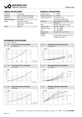
PERFORMANCE SPECIFICATIONS 2(T) 60
Oil viscosity u = 30 mm /s
2
p = f (Q) Pressure volume flow characteristics Q = f (I) Volume flow adjustment characteristics 1(P) 70
red
Q = 0,32 l/min Q = 0,32 l/min
N N
p [bar] Q [l/min] Cover „A” Star handle „G”
50 K0072 1 K0075 23 40
40 0.8
30 0.6
∆p = 20 bar
20 0.4 ∆p = 10 bar
10 0.2 ∆p = 5 bar
0 0
0 0.2 0.4 0.6 0.8 1 Q [l/min] 0 1 2 3 4 5 n [-] 25
44.6 55 26
p = f (Q) Pressure volume flow characteristics Q = f (I) Volume flow adjustment characteristics
red
Q = 3,2 l/min Q = 3,2 l/min
N N 73.6 84
p [bar] Q [l/min]
25 K0071 5 K0074
∆p = 20 bar
20 4
∆p = 10 bar
15 3
10 2 ∆p = 5 bar
5 1 HYDRAULIC CONNECTION PARTS LIST
Cavity drawing according to ISO 7789–18–01–0–98
0 0 Position Article Description
0 1 2 3 4 5 Q [l/min] 0 1 2 3 4 5 n [-] 20 114.2228 Control knob K9
M18x1.5
25 032.0616 Cover rd 23 / 3 x 35 K9
p = f (Q) Pressure volume flow characteristics Q = f (I) Volume flow adjustment characteristics 26 082.2004 Star handle rd 40 x 26
red
Q = 25 l/min Q = 25 l/min 30 193.1042 Retainer stainless rd 4 DIN 6799
N N
(2)
p [bar] Q [l/min] ∆p = 20 bar ∆p = 10 bar 40 153.1303 Hexagon nut 0,5d A4 M6 x 3,2
12.5 K0070 25 K0073 45 234.1060 Washer DIN 125A M6
10 20 (1) 50 160.2156 O-ring ID 15,60 x 1,78 (NBR)
7.5 15 ∆p = 5 bar 160.6156 O-ring ID 15,60 x 1,78 (FKM)
(1)
5 10 60 160.2111 O-ring ID 11,11 x 1,78 (NBR)
2.5 5 160.6111 O-ring ID 11,11 x 1,78 (FKM)
Note! For detailed cavity drawing and cavity tools see data
0 0 sheet 2.13-1002 70 049.3156 Backup ring rd 12,1 x 15 x 1,4
0 5 10 15 20 25 Q [l/min] 0 1 2 3 4 5 n [-]
www.wandfluh.com Illustrations are not binding Data subject to change 2/4 Edition: 19 39 2.4-510S E www.wandfluh.com Illustrations are not binding Data subject to change 3/4 Edition: 19 39 2.4-510S E
Page 1120