
Page 1003 - Softbound_Edition_19_en
P. 1003
Proportional pressure relief valve
Proportional pressure relief valve
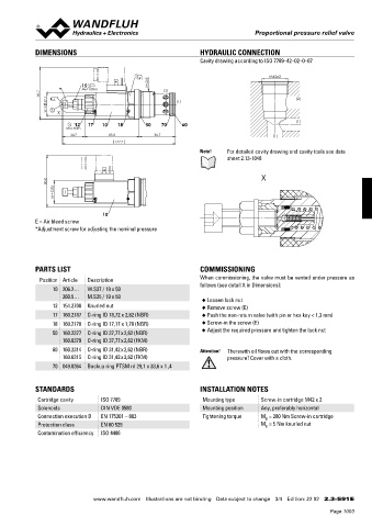
DIMENSIONS HYDRAULIC CONNECTION
Cavity drawing according to ISO 7789–42–02–0–07
s41 M42x2
15 M42x2
* MD=10Nm (2)
81.7
37.1 s6 (1) (2)
W = E X
(1)
12 17 10 18 50 70 60
MD=5Nm
34.7 85.8 56.7 (1)
177.2
Note! For detailed cavity drawing and cavity tools see data
sheet 2.13-1048
X
80.8
35
M =
10
E = Air bleed screw
*Adjustment screw for adjusting the nominal pressure
PARTS LIST COMMISSIONING
Position Article Description When commissioning, the valve must be vented under pressure as
follows (see detail X in Dimensions):
10 206.2… W.S37 / 19 x 50
260.5… M.S35 / 19 x 50
◆ Loosen lock nut
12 154.2700 Knurled nut ◆ Remove screw (E)
17 160.2187 O-ring ID 18,72 x 2,62 (NBR) ◆ Push the non-return valve (with pin or hex key < 1,3 mm)
18 160.2170 O-ring ID 17,17 x 1,78 (NBR) ◆ Screw-in the screw (E)
50 160.2377 O-ring ID 37,77 x 2,62 (NBR) ◆ Adjust the required pressure and tighten the lock nut
160.6379 O-ring ID 37,77 x 2,62 (FKM)
60 160.2314 O-ring ID 31,42 x 2,62 (NBR) Attention! Therewith oil flows out with the corresponding
160.6315 O-ring ID 31,42 x 2,62 (FKM) pressure! Cover with a cloth.
70 049.8364 Backup ring PTSM rd 29,1 x 33,6 x 1 ,4
STANDARDS INSTALLATION NOTES
Cartridge cavity ISO 7789 Mounting type Screw-in cartridge M42 x 2
Solenoids DIN VDE 0580 Mounting position Any, preferably horizontal
Connection execution D EN 175301 – 803 Tightening torque M = 280 Nm Screw-in cartridge
D
Protection class EN 60 529 M = 5 Nm knurled nut
D
Contamination efficiency ISO 4406
www.wandfluh.com Illustrations are not binding Data subject to change 3/4 Edition: 22 02 2.3-591 E
Page 1003