Page 976 - Softbound_Edition_19_en
P. 976

Proportional pressure relief valve
                                                                             Proportional pressure relief valve                                                                                           Proportional pressure relief valve


       GENERAL SPECIFICATIONS                              HYDRAULIC SPECIFICATIONS                                                DIMENSIONS                                           HYDRAULIC CONNECTION
       Designation        Proportional pressure relief valve  Working pressure  p  = 400 bar                                                                                            Cavity drawing according to ISO 7789–33–02–0–98
                                                                                max
       Construction       Pilot operated                    Tank pressure      p   = p  + 15 bar
                                                                                T max  P                                                                              s32                                    M33 x 2
       Mounting           Screw-in cartridge construction   Nominal pressure   P  = 100 bar, 200 bar, 275 bar, 350 bar
                                                                                N
       Nominal size       M33 x 2 according to ISO 7789     range                                                                         15                          M33x2
       Actuation          Proportional solenoid             Volume flow range  Q = 5…230 l/min                                        78.2   MD=5.5Nm                       (2)
       Ambient temperature  -25…+70 °C                      Leakage oil        See characteristics                                     37.1                                                                           (2)
       Weight             0,70 kg                           Hysteresis         ≤ 4 % at optimal dither signal                                                                    (1)
       MTTFd              150 years                         Repeatability      ≤ 2 % at optimal dither signal                           W=
                                                            Fluid              Mineral oil, other fluid on request                                                                                                    (1)
                                                                                                                                          12
                                                            Viscosity range    12 mm /s…320 mm /s                                      MD=5Nm  17    10     18       50     70    60                            (1)
                                                                                            2
                                                                                   2
                                                            Temperature range   -25…+70 °C (NBR)                                                         86.1             51.8
       ELECTRICAL SPECIFICATIONS                            fluid              -20…+70 °C (FKM)                                                               144.1                     Note!    For detailed cavity drawing and cavity tools see data
       Protection class   Connection execution D: IP65      Contamination      Class 18 / 16 / 13                                                                        HB0                     sheet 2.13-1041
                          Connection execution J: IP66      efficiency                                                                                                  15
                          Connection execution G: IP67 and IP69K  Filtration   Required filtration grade ß 6…10 ≥ 75,                                               MD= 9.5Nm
       Relative duty factor  100 % DF                                          see data sheet 1.0-50
       Standard nominal   12 VDC, 24 VDC                                                                                              77.3
       voltage                                                                                                                          35
       Limiting current at  I  = 1320 mA (U  = 12VDC)                                                                                    M =
                                     N
                           G
       50 °C              I  = 660 mA (U  = 24VDC)
                           G        N
                                                                                                                                                   10
       Note!   Other electrical specifications see data sheet 1.1-173
               (slip-on coil W) and 1.1-174 (slip-on coil M)
                                                                                                                                   PARTS LIST                                           ACCESSORIES
                                                                                                                                     Position Article  Description                       Proportional amplifier      Register 1.13
                                                                                                                                         10 206.2…  W.S37 / 19 x 50                      Electric plug B (black)     Article no. 219.2002
       PERFORMANCE SPECIFICATIONS                                                                                                           260.5…  M.S35 / 19 x 50                      Threaded body               Data sheet 2.9-200
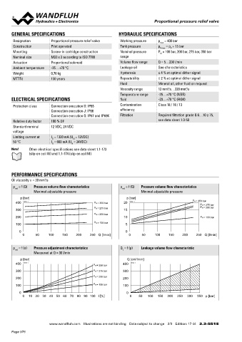
       Oil viscosity u = 30 mm /s
                       2
                                                                                                                                         12 154.2700  Knurled nut                        Technical explanations      Data sheet 1.0-100
       p  = f (Q)  Pressure volume flow characteristics     p  = f (Q)  Pressure volume flow characteristics                             15 253.8000  HB4,5 manual override              Hydraulic fluids            Data sheet 1.0-50
        red
                                                             red
                  Maximal adjustable pressure                         Minimal adjustable pressure                                           239.2033  HB0 Screw plug                     Filtration                  Data sheet 1.0-50
           p [bar]                                             p [bar]                                                                   17 160.2187  O-ring ID 18,72 x 2,62 (NBR)
         400  K0731_1                          P N = 350 bar  20  K0732_1                       P N = 350 bar
                                                                                                    P N = 275 bar                        18 160.2170  O-ring ID 17,17 x 1,78 (NBR)
                                               P N = 275 bar                                        P N = 200 bar
         300                                                  15                                                                         50 160.2298  O-ring ID 29,82 x 2,62 (NBR)      MANUAL OVERRIDE
                                               P N = 200 bar                                                                                160.6296  O-ring ID 29,82 x 2,62 (FMK)
         200                                                  10                                    P N = 100 bar                                                                       HB4,5
                                                                                                                                         60 160.2219  O-ring ID 21,89 x 2,62 (NBR)
                                               P N = 100 bar                                                                                                                            Optionally: Screw plug (HB0), no actuation possible
         100                                                   5                                                                            160.6216  O-ring ID 21,89 x 2,62 (FKM)
           0                                                   0                                                                         70 049.3277  Backup ring rd 22,5 x 27 x 1,4
            0      50    100    150   200    250 Q [l/min]      0      50    100    150    200    250 Q [l/min]

                                                                                                                                   SURFACE TREATMENT                                    SEALING MATERIAL
       p  = f (n)  Pressure adjustment characteristics      Q  = f (p)  Leakage volume flow characteristic
        red                                                  L                                                                        The cartridge body, the slip-on coil and the armature tube are   NBR or FKM (Viton) as standard, choice in the type code
                  Measured at Q = 30 l/min                                                                                          ◆
                                                                                                                                      zinc-nickel coated
           p [bar]                                              Q [cm /min]
                                                                    3
         400  K0733_1                          P N = 350 bar  400  K0734_1
                                                                                                                                   STANDARDS                                            INSTALLATION NOTES
         300                                   P N = 275 bar  300
                                                                                                                                    Cartridge cavity    ISO 7789                         Mounting type      Screw-in cartridge M33 x 2
         200                                   P N = 200 bar  200                                                                   Solenoids           DIN VDE 0580                     Mounting position  Any, preferably horizontal
         100                                   P N = 100 bar  100                                                                   Connection execution D  EN 175301 – 803              Tightening torque  M  = 80 Nm Screw-in cartridge
                                                                                                                                                                                                             D
                                                                                                                                    Protection class    EN 60 529                                           M  = 5 Nm knurled nut
                                                                                                                                                                                                             D
           0                                                   0                                                                                                                                            M  = 9,5 Nm HB0
            0   10  20  30  40 50 60 70 80 90  100 l [%]         0   50   100  150  200  250  300  350 p [bar]                      Contamination efficiency  ISO 4406                                       D
                                                                                                                                                                                                            M  = 5,5 Nm HB4,5
                                                                                                                                                                                                             D
                                                                                                                                                                                        Wandfluh AG  Postfach  CH-3714 Frutigen
                                                                                                                                                                                        Tel. +41 33 672 72 72  Fax +41 33 672 72 12  sales@wandfluh.com

                         www.wandfluh.com  Illustrations are not binding  Data subject to change  2/3  Edition: 17 44  2.3-551 E                      www.wandfluh.com  Illustrations are not binding  Data subject to change  3/3  Edition: 17 44  2.3-551 E
       Page 976
   971   972   973   974   975   976   977   978   979   980   981