Page 972 - Softbound_Edition_19_en
P. 972

Proportional pressure relief valve
                                                                             Proportional pressure relief valve                                                                                           Proportional pressure relief valve


       GENERAL SPECIFICATIONS                              HYDRAULIC SPECIFICATIONS                                                DIMENSIONS
       Designation        Proprtional pressure relief valve with   Working pressure  p  = 400 bar
                                                                                max
                          inverse function                  Nominal pressure   P  = 20 bar, 100 bar, 160 bar, 200 bar, 315                                                                           X
                                                                                N
       Construction       Direct operated                   range              bar, 350 bar                                                                              s30
       Mounting           Screw-in cartridge construction                      Adjustable via adjustment screw (-20 %                        15
       Nominal size       M22 x 1,5 according to ISO 7789                      / +30 %)                                               76.8   MD=10Nm                      M22x1.5
       Actuation          Proportional solenoid             Maximum volume flow  Q  = 25 l/min (p  = 20 / 100 / 160 / 200              37.1   s6                             (2)
                                                                                max
                                                                                           N
       Ambient temperature  -25…+70 °C                                         bar)                                                      E                                       (1)
       Weight             0,60 kg                                              Q  = 15 l/min (p  = 315 / 350 bar)                       W =  X  *
                                                                                           N
                                                                                max
                                                                               Q  = 5 l/min
       MTTFd              150 years                                             max                                                                                                     HYDRAULIC CONNECTION
                                                            Minimum volume flow  Q  = 0,2 l/min                                                  12   17    10    18     50  70   60    Cavity drawing according to ISO 7789–22–02–0–98
                                                                                min
                                                            Leakage oil        See characteristics                                            MD=5Nm
                                                            Hysteresis         ≤ 4 % at optimal dither signal                                    34.7         78.4           37
       ELECTRICAL SPECIFICATIONS                                                                                                                              150.1                                           M22x1.5
                                                            Repeatability      ≤ 2 % at optimal dither signal
       Protection class   Connection execution D: IP65      Fluid              Mineral oil, other fluid on request
                          Connection execution J: IP66      Viscosity range    12 mm /s…320 mm /s
                                                                                   2
                                                                                            2
                          Connection execution G: IP67 and IP69K                                                                                                                                                       (2)
       Relative duty factor  100 % DF                       Temperature range   -25…+70 °C (NBR)
                                                                               -20…+70 °C (FKM)
                                                            fluid
       Standard nominal   12 VDC, 24 VDC                    Contamination      Class 18 / 16 / 13                                      74.8                                                                            (1)
       voltage                                              efficiency                                                                  35
       Limiting current at  I  = 1320 mA (U  = 12VDC)       Filtration         Required filtration grade ß 6…10 ≥ 75,                    M =                                                                  (1)
                           G
                                     N
       50 °C              I  = 660 mA (U  = 24VDC)
                           G        N                                          see data sheet 1.0-50
       Note!   Other electrical specifications see data sheet 1.1-173                                                                                     10                            Note!    For detailed cavity drawing and cavity tools see data
               (slip-on coil W) and 1.1-174 (slip-on coil M)                                                                       E = Air bleed screw                                           sheet 2.13-1003
                                                                                                                                   *Adjustment screw for adjusting the nominal pressure
       PERFORMANCE SPECIFICATIONS
       Oil viscosity u = 30 mm /s                                                                                                  PARTS LIST                                           COMMISSIONING
                       2
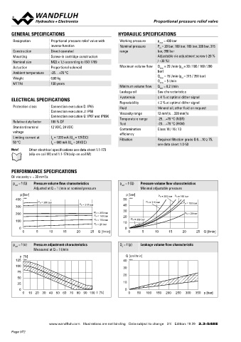
       p  = f (Q)  Pressure volume flow characteristics     p  = f (Q)  Pressure volume flow characteristics                                                                            When commissioning, the valve must be vented under pressure as
        red                                                  red                                                                     Position Article  Description
                  Adjusted at Q = 1 l/min at nominal pressure         Minimal adjustable pressure                                                                                       follows (see detail X in Dimensions):
                                                                                                                                         10 206.2…  W.S37 / 19 x 50
           p [bar]                                             p [bar]         P N = 200 bar  P N = 160 bar                                 260.5…  M.S35 / 19 x 50
         400  K0842                                           50  K0843                                                                                                                  ◆  Loosen lock nut
                    P N = 350 bar                                        P N = 315 bar      P N = 100 bar                                   154.2700  Knurled nut                        ◆  Remove screw (E)
         300                            P N = 315 bar         40                                                                            153.2401  Dichtmutter Norm „Seal-Lock” 8 Zi - Ni M8   Push the non-return valve (with pin or hex key < 1,3 mm)
                                                              30                                                                                                                         ◆
         200                                    P N = 200 bar                               P N = 20 bar                                    160.2187  O-ring ID 18,72 x 2,62 (NBR)       ◆  Screw-in the screw (E)
                                                P N = 160 bar  20                                                                                                                          Adjust the required pressure and tighten the lock nut
         100                                    P N = 100 bar  10  P N = 350 bar                                                            160.2170  O-ring ID 17,17 x 1,78 (NBR)       ◆
                                                P N = 20 bar                                                                                160.2188  O-ring ID 18,77 x 1,78 (NBR)
           0                                                   0
            0      5     10     15     20     25  Q [l/min]     0      5      10    15     20     25  Q [l/min]                             160.6188  O-ring ID 18,77 x 1,78 (FKM)      Attention!  Therewith oil flows out with the corresponding
                                                                                                                                            160.2140  O-ring ID 14,00 x 1,78 (NBR)               pressure! Cover with a cloth.
                                                                                                                                            160.6141  O-ring ID 14,00 x 1,78 (FKM)
       p  = f (n)  Pressure adjustment characteristics      Q  = f (p)  Leakage volume flow characteristic
        red                                                  L                                                                              049.3177  Back-up ring rd 14,6 x 17,5 x 1,4
                  Measured at Q = 1 l/min
           p  [%]                                              Q [cm /min]
                                                                   3
         125  K0844                                           40  K0845
         100                                                  30
          75
                                                              20
          50
          25                                                  10
           0                                                   0
            0   10  20  30  40 50 60 70 80 90  100 I  [%]       0    50  100  150  200  250  300  350 p [bar]


                         www.wandfluh.com  Illustrations are not binding  Data subject to change  2/4  Edition: 19 29  2.3-548 E                      www.wandfluh.com  Illustrations are not binding  Data subject to change  3/4  Edition: 19 29  2.3-548 E
       Page 972
   967   968   969   970   971   972   973   974   975   976   977