
Page 973 - Softbound_Edition_19_en
P. 973
Proportional pressure relief valve
Proportional pressure relief valve
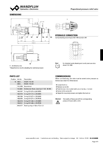
DIMENSIONS
X
s30
15 M22x1.5
76.8 MD=10Nm (2)
37.1 E s6 (1)
W = X *
HYDRAULIC CONNECTION
12 17 10 18 50 70 60 Cavity drawing according to ISO 7789–22–02–0–98
MD=5Nm
34.7 78.4 37
M22x1.5
150.1
(2)
74.8 (1)
35
M = (1)
10 Note! For detailed cavity drawing and cavity tools see data
E = Air bleed screw sheet 2.13-1003
*Adjustment screw for adjusting the nominal pressure
PARTS LIST COMMISSIONING
Position Article Description When commissioning, the valve must be vented under pressure as
follows (see detail X in Dimensions):
10 206.2… W.S37 / 19 x 50
260.5… M.S35 / 19 x 50
◆ Loosen lock nut
154.2700 Knurled nut ◆ Remove screw (E)
153.2401 Dichtmutter Norm „Seal-Lock” 8 Zi - Ni M8 ◆ Push the non-return valve (with pin or hex key < 1,3 mm)
160.2187 O-ring ID 18,72 x 2,62 (NBR) ◆ Screw-in the screw (E)
160.2170 O-ring ID 17,17 x 1,78 (NBR) ◆ Adjust the required pressure and tighten the lock nut
160.2188 O-ring ID 18,77 x 1,78 (NBR)
160.6188 O-ring ID 18,77 x 1,78 (FKM) Attention! Therewith oil flows out with the corresponding
160.2140 O-ring ID 14,00 x 1,78 (NBR) pressure! Cover with a cloth.
160.6141 O-ring ID 14,00 x 1,78 (FKM)
049.3177 Back-up ring rd 14,6 x 17,5 x 1,4
www.wandfluh.com Illustrations are not binding Data subject to change 3/4 Edition: 19 29 2.3-548 E
Page 973