
Page 848 - Softbound_Edition_19_en
P. 848
BV.PM33
Pressure relief valve BV.PM33
GENERAL SPECIFICATIONS HYDRAULIC SPECIFICATIONS DIMENSIONS
Designation Pressure relief valve Working pressure p = 400 bar Key adjustment «S» Control knob adjustment «D»
max
Construction Pilot operated Tank pressure p p + 20 bar 17 s4
T max P
Mounting Screw-in cartridge construction Nominal pressure p = 160 bar, 350 bar 30
N
Nominal size M33 x 2 according to ISO 7789 range 40
Actuation Manually Minimum pressure See characteristics s13 20
Ambient temperature -25…+90 °C Volume flow range Q = 0,2…230 l/min s24
Weight 0,37 kg key adjustment Leakage oil See characteristics 54
0,38 kg control knob adjustment Fluid Mineral oil, other fluid on request s32
0,44 kg cover Viscosity range 12 mm /s…320 mm /s
2
2
MTTFd 150 years Temperature range -25…+90 °C (NBR) Ø40
fluid -20…+90 °C (FKM) 106
Contamination Class 18 / 16 / 13 M33x2 50
efficiency
Filtration Required filtration grade ß 6…10 ≥ 75, 52
see data sheet 1.0-50 2(T)
70
PERFORMANCE SPECIFICATIONS 60
Oil viscosity u = 30 mm /s 1(P)
2
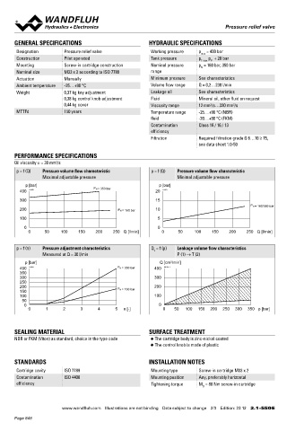
p = f (Q) Pressure volume flow characteristic p = f (Q) Pressure volume flow characteristic
Maximal adjustable pressure Minimal adjustable pressure Cover «A» HYDRAULIC CONNECTION
Cavity drawing according to ISO 7789–33–02–0
p [bar] P N = 350 bar p [bar]
400 K1150 20 K1151
M33 x 2
300 15
P N = 160/350 bar 25
200 P N = 160 bar 10
100 5 (2)
0 0
0 50 100 150 200 250 Q [l/min] 0 50 100 150 200 250 Q [l/min]
(1)
(1)
p = f (n) Pressure adjustment characteristics Q = f (p) Leakage volume flow characteristics
L
Measured at Q = 30 l/min P (1) → T (2) Note! For detailed cavity drawing and cavity tools see data
sheet 2.13-1041
p [bar] Q [cm /min]
3
400 K1152 P N = 350 bar 400 K0734_1
350
300 300
250
200 200 PARTS LIST ACCESSORIES
150 P N = 160 bar
100 100 Position Article Description Verstellarten für Schraubpatronen Data sheet 2.0-50
50 20 114.2224 Control knob Threaded body Data sheet 2.9-200
0 0
0 1 2 3 4 5 n [-] 0 50 100 150 200 250 300 350 p [bar] 25 032.0611 Cover rd 23 / 3 x 35 Technical explanations Data sheet 1.0-100
30 193.1061 Retainer rd 6 DIN 6799 Hydraulic fluids Data sheet 1.0-50
40 153.1402 Hexagon nut 0,5d M8 x 1 Filtration Data sheet 1.0-50
SEALING MATERIAL SURFACE TREATMENT - 251.3228 Seal kit
NBR or FKM (Viton) as standard, choice in the type code ◆ The cartridge body is zinc-nickel coated
◆ The control knob is made of plastic Seal kit consisting of
50 O-ring ID 29,82 x 2,62
60 O-ring ID 21,89 x 2,62
STANDARDS INSTALLATION NOTES 70 Backup ring rd 22,5 x 27 x 1,4
Cartridge cavity ISO 7789 Mounting type Screw-in cartridge M33 x 2
Contamination ISO 4406 Mounting position Any, preferably horizontal
efficiency Tightening torque M = 80 Nm screw-in cartridge
D
Wandfluh AG Postfach CH-3714 Frutigen
Tel. +41 33 672 72 72 Fax +41 33 672 72 12 sales@wandfluh.com
www.wandfluh.com Illustrations are not binding Data subject to change 2/3 Edition: 23 12 2.1-550 E www.wandfluh.com Illustrations are not binding Data subject to change 3/3 Edition: 23 12 2.1-550 E
Page 848