
Page 358 - Softbound_Edition_19_en
P. 358
Proportional spool valve
Proportional spool valve Proportional spool valve
PERFORMANCE SPECIFICATIONS INSTALLATION NOTES MANUAL OVERRIDE
Oil viscosity u = 30 mm /s Mounting type Flange mounting ◆ Integrated (–) Actuation pin integrated in the armature tube.
2
Actuation by pressing the pin
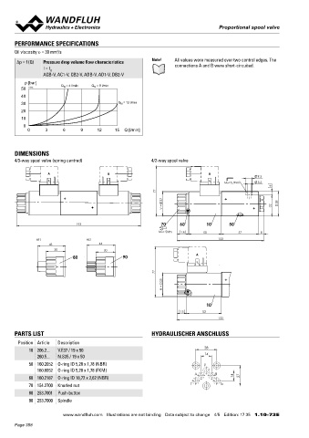
Δp = f (Q) Pressure drop volume flow characteristics Note! All values were measured over two control edges. The 3 fixing holes for ◆ Push-button (HF1) Integrated in the knurled nut. Actuation by
I = I G connections A and B were short-circuited. socket head screws M5 x 40 pressing the push-button
ACB-V, AC1-V, CB2-V, ADB-V, AD1-V, DB2-V Mounting position Any, preferably horizontal ◆ Spindle (HS1) Integrated in the knurled nut. Actuation by turning
Tightening torque M = 5,2 Nm (screw quality 8.8, zinc
p [bar] Q = 8 l/min D the spindle (continuously variable valve actuation)
50 K4045 Q N = 4 l/min N coated) Fixing screws Attention! The actuation of the manual override is possible up to a
M = 5 Nm knurled nut
40 D tank pressure of:
30 Q N = 12 l/min Note! The length of the fixing screw depends on the base 160 bar Integrated (–)
material of the connection element. 160 bar Push-button (HF1)
20 160 bar Spindle (HS1)
10
0
0 3 6 9 12 15 Q [l/min] STANDARDS ACCESSORIES
Mounting interface Wandfluh standard Mating connector grey (A) Article no. 219.2001
Solenoids DIN VDE 0580 Mating connector black (B) Article no. 219.2002
DIMENSIONS Connection execution D EN 175301 – 803 Threaded subplates Data sheet 2.9-10
4/3-way spool valve (spring centred) 4/2-way spool valve Protection class EN 60 529 Multi-station subplates Data sheet 2.9-50
Contamination efficiency ISO 4406 Horizontal mounting blocks Data sheet 2.9-90
A B A
9.5 Explications techniques Data sheet 1.0-100
MD=5.2Nm 5.2
6 Hydraulic fluids Data sheet 1.0-50
77 Filtration Data sheet 1.0-50
37 38 Relative duty factor Data sheet 1.1-430
V = 32 Proportional amplifier Register 1.13
193 70 60 10 50
MD= 5Nm 18 50 57 8 SURFACE TREATMENT SEALING MATERIAL
HF1 HS1 133 ◆ The valve body is painted with a two component paint NBR or FKM (Viton) as standard, choice in the type code
43 44 ◆ The armature tube and the plug screw are zinc coated
30 30 The slip-on coil is zinc-nickel coated
80 90 A ◆
77
35
N =
10
15 53
133
PARTS LIST HYDRAULISCHER ANSCHLUSS
Position Article Description
28
10 206.2... V.E37 / 19 x 50
260.5... N.S35 / 19 x 50 14
50 160.2052 O-ring ID 5,28 x 1,78 (NBR) P
160.6052 O-ring ID 5,28 x 1,78 (FKM)
A B
60 160.2187 O-ring ID 18,72 x 2,62 (NBR) 14 27
70 154.2700 Knurled nut T T0
80 253.7001 Push-button
90 253.7000 Spindle Wandfluh AG Postfach CH-3714 Frutigen
Tel. +41 33 672 72 72 Fax +41 33 672 72 12 sales@wandfluh.com
www.wandfluh.com Illustrations are not binding Data subject to change 4/5 Edition: 17 35 1.10-73 E www.wandfluh.com Illustrations are not binding Data subject to change 5/5 Edition: 17 35 1.10-73 E
Page 358