
Page 352 - Softbound_Edition_19_en
P. 352
Proportional spool valve
Proportional spool valve Proportional spool valve
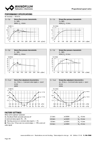
PERFORMANCE SPECIFICATIONS Frequency response Note! All values were measured over two control edges. The
Oil viscosity u = 30 mm /s ∆p = 10 bar connections A and B were short-circuited.
2
Q = f (p) Volume flow pressure characteristic Q = f (p) Volume flow pressure characteristic p < 1 bar
T
S = 100% S = 100% Amplitude [dB] Phase [ ]
o
S4D41, Q = 4 l/min V4D42, Q = 4 l/min 2 K0912_1_e
N
N
Q [l/min] Q [l/min] 0
15 K0189_1 15 K0200_1 180
12.5 12.5 -3
10 10 -6 90
7.5 7.5
5 5 -9 0 0,5 1 5 10 0
2.5 2.5 Signal amplitude 90% 50 100 Frequency [Hz]
Signal amplitude 10%
0 0
0 50 100 150 200 250 300 350 p [bar] 0 50 100 150 200 250 300 350 p [bar]
DIMENSIONS HYDRAULIC CONNECTION
With analog interface, 12 pole connector
Q = f (p) Volume flow pressure characteristic Q = f (p) Volume flow pressure characteristic Amplifier and controller 28
S = 100% S = 100% 25,30 20,21 40 14
S4D41, Q = 8 l/min V4D42, Q = 8 l/min
N N
X2
Q [l/min] Q [l/min] X1** MD= 5.2Nm P
30 K0188_1 30 K0199_1 X1* A B
25 25 X4*** 14 27
20 20 101.9 9.5 6 T T0
15 15 69
10 10 35 32 38
5 5
0 0 65 MD= 2.6Nm 50 5.2 60 MD= 2.6Nm
0 50 100 150 200 250 300 350 p [bar] 0 50 100 150 200 250 300 350 p [bar] 10 102.5 64
* For amplifier
** For controller
*** Only controller
Q = f (s,x) Volume flow adjustment characteristics Q = f (s,x) Volume flow adjustment characteristics
∆p = 10 bar, s = Command value signal, x = spool ∆p = 10 bar, s = Command value signal, x = spool With analog interface, 7 pole connector With fieldbus interface With fieldbus interface
stroke stroke Amplifier and controller Amplifier Controller
S4D41 V4D42
X2 X2
Q [l/min] Q [l/min] X1
7,5 K0775_1 7,5 K0776_1 Q = 8 l/min X1** X1* X2
N
6 Q = 8 l/min 6 N X1 X3
4,5 4,5 119.9 X4*** 101.9 X3 119.9 X4
3 Q N = 4 l/min 3 Q N = 4 l/min
1,5 1,5 35 35 35
-100 -80 -60 -40 -20 0 20 40 60 80 100 x [%] -100 -80 -60 -40 -20 0 20 40 60 80 100 x [%]
6.1 5.2 5.2
-100 -76 -52 -28 -4 0 4 28 52 76 100 s [%] -100 -76 -52 -28 -4 0 4 28 52 76 100 s [%]
FACTORY SETTINGS
Dither set for optimum hysteresis
◆ = Deadband: Both solenoids switched off 2,1 l/min at S4D41 Q = 4 l/min
N
at command value signal -2%… 2% 4,5 l/min at S4D41 Q = 8 l/min
N
● = Opening pressure at command value signal + / - 4% 1,9 l/min at S4D41 Q = 4 l/min
N
■ = Flow at ∆p = 10 bar over two control edges + / - 70% command 4,5 l/min at S4D41 Q = 8 l/min
value signal N
www.wandfluh.com Illustrations are not binding Data subject to change 4/6 Edition: 21 48 1.10-70 E www.wandfluh.com Illustrations are not binding Data subject to change 5/6 Edition: 21 48 1.10-70 E
Page 352