
Page 315 - Softbound_Edition_19_en
P. 315
Spool valve
Spool valve
ACTUATION INSTALLATION NOTES
Actuation Hydraulically operated Mounting type Flange mounting
Pilot pressure Recommended p = 20 bar 4 fixing holes for
v
∆p (x-y) < 3 bar for a stable position socket head screws M6 x 40
∆p (x-y) > 12 bar for secure switching Mounting position Any, preferably horizontal
Tightening torque M = 10.5 Nm ± 10 %, quality 8.8
D
Note! The length of the fixing screw depends on the base
material of the connection element.
PERFORMANCE SPECIFICATIONS
Oil viscosity u = 30 mm /s
2
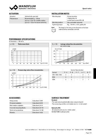
p = f (Q) Performance limits Q = f (Q) Leakage volume flow characteristics
L
per control edge
p [bar] Q [cm /min]
3
350 K4263 200 K4264
300
250 150
200 100
150
100 50
50
0 0
0 20 40 60 80 100 120 140 160 Q [l/min] 0 50 100 150 200 250 300 350 p [bar]
Δp = f (Q) Pressure drop-volume flow characteristics Volume flow direction
∆p [bar] Symbol P - A P - B P - T A - T B - T
20 K4265 1 BA1 / BA2 / BA3 3 3 - 2 1
BCA 3 3 - 2 1
15 2
3 BDA 3 3 - 2 1
10
5
0
0 20 40 60 80 100 120 140 160 Q [l/min]
ACCESSORIES SURFACE TREATMENT
Fixing screws Data sheet 1.0-60 Standard:
Threaded subplates Data sheet 2.9-40 -The valve body is painted with a two component paint
-The screw plug and the control plate are zinc-nickel coated
Multi-station subplates Data sheet 2.9-70
Horizontal mounting blocks Data sheet 2.9-110 Optionally (K8):
Technical explanations Data sheet 1.0-100 -All external parts are zinc-nickel coated
ISO 9227 (800 h) salt spray test
Filtration Data sheet 1.0-50
www.wandfluh.com Illustrations are not binding Data subject to change 3/4 Edition: 22 09 1.7-42 E
Page 315