
Page 758 - Softbound_Edition_19_en
P. 758
Mobile electronics
Mobile electronics MD2
Description of the «MD2»-amplifier electronics
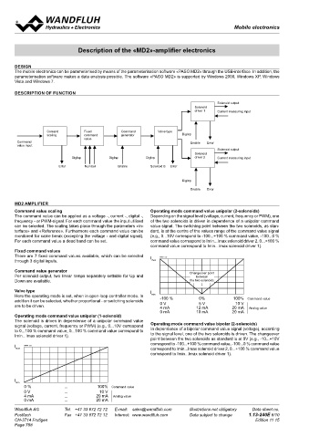
DESIGN
The mobile electronics can be parameterised by means of the parameterisation software «PASO MD2» through the USB-interface. In addition, the
parameterisation software makes a data analysis possible. The software «PASO MD2» is supported by Windows 2000, Windows XP, Windows
Vista and Windows 7.
DESCRIPTION OF FUNCTION
Solenoid output
Solenoid
driver 1 Current measuring input
Comand Fixed Command Valve type
scaling command generator DigInp
value
Command Enable Error
value input
Solenoid output
Solenoid
DigInp DigInp DigInp driver 2 Current measuring input
Error Number Enable Solenoid B Error
DigInp
Enable Error
MD2 AMPLIFIER
Command value scaling Operating mode command value unipolar (2-solenoids)
The command value can be applied as a voltage -, current -, digital -, Depending on the signal level (voltage, current, frequency or PWM), one
frequency - or PWM-signal. For each command value the input utilised of the two solenoids is driven in dependence of a unipolar command
can be selected. The scaling takes place through the parameters «In- value signal. The switching point between the two solenoids, as stan-
terface» and «Reference». Furthermore each command value can be dard, is at the centre of the values range of the command value signal
monitored for cable break (excepting the voltage - and digital signal). (e.g., 0...10V correspond to -100...+100 % command value, -100...0 %
For each command value a dead band can be set. command value correspond to Imin...Imax solenoid driver 2, 0...+100 %
command value correspond to Imin...Imax solenoid driver 1).
Fixed command values
There are 7 fixed command values available, which can be selected I K0932_e.ai
through 3 digital inputs. max
Command value generator Changeover point
Per solenoid output, two linear ramps separately settable for Up and between
Down are available. the two solenoids
↓
Valve type I
Here the operating mode is set, when in open-loop controller mode. In min -100 % 0%
addition it can be selected, whether proportional - or switching solenoids 100% Command value
5 V
10 V
are to be driven. 0 V 12 mA 20 mA Analog value
4 mA
0 mA 10 mA 20 mA
Operating mode command value unipolar (1-solenoid)
The solenoid is driven in dependence of a unipolar command value
signal (voltage, current, frequency or PWM) (e.g., 0...10V correspond Operating mode command value bipolar (2-solenoids)
to 0...100 % command value, 0...100 % command value correspond to In dependence of a bipolar command value signal (voltage), according
Imin...Imax solenoid driver 1). to the signal level, one of the two solenoids is driven. The changeover
point between the two solenoids as standard is at 0V (e.g., -10...+10V
correspond to -100...+100 % command value, -100...0 % command value
I K0930_e.ai
max correspond to Imin...Imax solenoid driver 2, 0...+100 % command value
correspond to Imin...Imax solenoid driver 1).
I
min
0 % ... 100% Command value
0 V ... 10 V
4 mA ... 20 mA Analog value
0 mA ... 20 mA
Wandfluh AG Tel. +41 33 672 72 72 E-mail: sales@wandfluh.com Illustrations not obligatory Data sheet no.
Postfach Fax +41 33 672 72 12 Internet: www.wandfluh.com Data subject to change 1.13-240E 6/10
CH-3714 Frutigen Edition 11 15
Page 758