
Page 761 - Softbound_Edition_19_en
P. 761
Mobile electronics MD2
Mobile electronics
Description of the amplifier – and controller electronics «MD2»
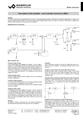
DESIGN
The mobile electronics can be parameterised by means of the parameterisation software «PASO MD2» through the USB-interface. In addition, the
parameterisation software makes a data analysis possible, with integrated graphic signal recording. The software «PASO MD2» is supported by
Windows 2000, Windows XP, Windows Vista and Windows 7.
DESCRIPTION OF FUNCTION
Solenoid output
Solenoid
driver 1
Current measuring
input
Command Fixed Command Controller Valve type
value scaling command generator
value
Command Enable Error
value
input Solenoid output
Solenoid
DigInp DigInp DigInp driver 2
Error Number Enable Solenoid B Current measuring
input
DigInp
Feedback
scaling
Enable Error
Feedback
value Window
input Display
Error
MD2 CONTROLLER
Command value scaling Controller
The command value can be applied as a voltage -, current -, digital -, Two (for the Basic version) or four (for the Enhanced version) con-
frequency - or PWM-signal. For each command value the input utilised troller circuits are available. The following controller modes can be
can be selected. The scaling takes place through the parameters «In- selected:
terface» and «Reference». Furthermore each command value can be
monitored for cable break (excepting the voltage - and digital signal). Controller mode 3 «Pressure / volume flow valve control»
In the version with CAN-connection, the command value can also be Driving of a pressure relief -, pressure control -, throttle - or flow control
digitally transmitted. valve in the open control circuit (without feedback value return). The
number of solenoids that are driven is dependent on the selected
Fixed command values operating mode.
There are 7 fixed command values available, which can be selected
through 3 digital inputs. Controller mode 4 «Pressure / volume flow valve control (1-solenoid)»
P Driving of a 1-solenoid pressure relief -, pressure control -, throttle - or
Command value generator flow control valve in the closed control circuit (with feedback value
In the open-loop controller modes, two linear ramps separately settable return). With it, only one solenoid can be driven (corresponds to the
MD2
w
for Up and Down are available per solenoid output. P Xi solenoid driver 1).
In the closed-loop controller modes, a positive and a negative travelling P Q
x
speed are available.
t Q
Xi
Feedback value scaling P Xi MD2 w Xi MD2 w
The feedback value can be applied as a voltage -, current -, frequency Q
x
- or PWM-signal. For each feedback signal the input utilised can be
MD2
selected. The scaling takes place through the parameters «Interface» Q
t
Xi
and «Reference». Furthermore each command value can be monito- Xi MD2 w
red for cable break (excepting the voltage signal). In the version with
w
CAN-connection, the feedback value can be read-in by a sensor with
CAN interface. MD2
Controller mode -5 «Pressure control (2-solenoids)»
Windows w P Driving of two 1-solenoid throttle valves in the closed control circuit
Available are a target -, contouring error - and solenoid-off window. In (with feedback value return) as pressure reduction. In doing so, one
V
Xi
each window the threshold and the delay time can be adjusted. P of the throttle valves serves as the charge - and the other one as
Xi the discharge valve. The charge valve corresponds to the solenoid
w P
P
driver 1, the discharge valve to the solenoid driver 2 (graphics on the
V following page).
Xi MD2
MD2 P Xi
Wandfluh AG Tel. +41 33 672 72 72 w E-mail: sales@wandfluh.com Illustrations not obligatory Data sheet no. P
Postfach Fax +41 33 672 72 12 Internet: www.wandfluh.com Data subject to change P 1.13-240E 9/10
w
CH-3714 Frutigen MD2 Xi Edition 11 15
MD2 Page 761
P MD2
w P
Xi
w
w P
Xi t MD2
Xi
MD2 w
w
Xi MD2 t
Xi
MD2 w
MD2
w