
Page 307 - Softbound_Edition_19_en
P. 307
Spool valve
Spool valve
PERFORMANCE SPECIFICATIONS
Oil viscosity u = 30 mm /s
2
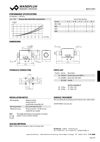
Δp = f (Q) Pressure drop-volume flow characteristics Volume flow direction
∆p [bar] Symbol P - A P - B P - T A - T B - T
25 K4256 1 AB1 / AB2 2 2 - 3 3
20 2 AB3 1 1 - 2 2
3
15 4 ACB 2 2 - 3 3
10 ADB 2 2 - 4 4
5
0
0 10 20 30 40 50 60 70 80 Q [l/min]
DIMENSIONS
9.5
5.2 MD=60Nm15 15 MD=60Nm
MD= 5.2Nm
8
G1/4"
41 49
23.5
50 60
10 50 60 10 46 30.1 68 30.1
MD=60Nm MD=60Nm
12.6 68 12.6 128.2
93.2
HYDRAULIC CONNECTION PARTS LIST
Position Article Description
17.8
10 239.2210 Socket head screw M20 x 1
T 6.5 15 032.4818 Bush rd 24 / M3 x 38,5
6.5 251.2225 Seal kit
31 x A B y 21 32.5
P
Seal kit consisting of
21.5 50 O-Ring ID 9,25 x 1,78
40.5 60 O-Ring ID 5,28 x 1,78
INSTALLATION NOTES SURFACE TREATMENT
Mounting type Flange mounting The valve body, the screw plug and the bush are zinc-nickel coated
4 fixing holes for
socket head screws M5 x 50 ISO 9227 (800 h) salt spray test
Mounting position Any, preferably horizontal
Tightening torque Fixing screws M = 5,2 Nm (screw
D
quality 8.8, zinc coated)
Note! The length of the fixing screw depends on the base
material of the connection element.
SEALING MATERIAL
NBR or FKM (Viton) as standard, choice in the type code
Wandfluh AG Postfach CH-3714 Frutigen
Tel. +41 33 672 72 72 Fax +41 33 672 72 12 sales@wandfluh.com
www.wandfluh.com Illustrations are not binding Data subject to change 3/3 Edition: 23 12 1.7-32 E
Page 307